


LC meter - LC100x User Guide

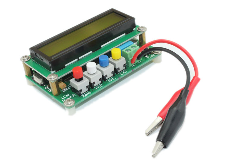
Engaged in electronic development engineers often need to measure inductors and capacitors, however the inductors&Cap meter selling expensive on the market, and there are larger error in measurement of small inductors and small capacitors. This LC100x meter base on LC resonant principle, and adding high-speed precision measurement of micro-controller calculated to measure less than 1uH inductance and less than 1pF capacitors. It's easy to use and let's take a look. You can get it from store.


1. 5V Power socket : Used 5V DC Adapter for power supply
2. Mini USB socket: Used miniUSB for power supply
3. 1602 LCD: 16x2 LCM for Display
4. Power Switch : Power On / Off
5. Reserve Button: Reserved for future
6. Test side
7. Red E-Lock Button : The Button is auto-E-lock for Clear display and measure data, press down is '1' and release it is '0', details as figure 1
8. White E-Lock Button : The Button is auto-E-lock for Select Large(High) Capacitance , press down is '1' and release it is '0', details as figure 1
9. Blue E-Lock Button : The Button is auto-E-lock for Select Large(High) Inductance, press down is '1' and release it is '0', details as figure 1
10. Yellow E-Lock Button : The Button is auto-E-lock for Select Inductance or Capacitance, press down is '1' and release it is '0', details as figure 1

Figure 1
Operating Guide
1. Connect to miniUSB or 5V adapter for Power supply, and switch to Power On .
2. Open circuit,from the LCD display
L Stall display MEASURE Lx OVER RANGE C Stall display MEASURE Cx 0.00pF Hi L Stall display MEASURE Hi.L OVER RANGE Hi C Stall diaplay MEASURE Hi.C 0.00uF If you short circuit of the test side, the display as below: Hi L Stall display MEASURE Hi.L 0.000mH L Stall display MEASURE Lx 0.000uH C Stall display MEASURE Cx OVER RANGE If you have short circuit, but the L Stall is not display Zero, or Open circuit the C Stall not display Zero, the must press down "Clear Button", the details option as below: a). C Stall mode Keeping Open circuit, and press down the first Red Clear Button - "Zero" , there will show "CALCULATING…", please hold on over 2S until show "CALCULATING…OK". Go on keep hold on until show 'DATA SAVED' . That's means complete the process, LCD show 0.00pF, then, you can connect the capacitor under test. b).L Stall mode Keeping Short circuit, and press down the first Red Clear Button - "Zero" , there will show "CALCULATING…", please hold on over 2S until show "CALCULATING…OK". Go on keep hold on until show 'DATA SAVED' . That's means complete the process, LCD show0.000uH or 0.000mH, then, you can connect the capacitor under test.
3. Note : Measuring small capacitance and inductance, the impact test line can "Zero" to eliminate. You can keep the device under same attitude as you can to maximize the elimination of error caused by the test line.
4. When the results of the measurement be displayed, press the black function keys(Reserve Button) will display the current test frequency.
5. In Hi C stalls, make sure that the capacitor has fully discharged before under test. Red test clip for the capacitor positive , the black test clip for the capacitor negative. If capacitor over 10mF, the test time may over 1S, the capacitor over 100mF, the test time may over 7~8S.
Physical Test
1. First, we used LC100-A test the big Capacitor. There are six 4700uF capacitor in parallel, and the measurements is 28.7mF. Equivalent to each capacitor is 4.78mF. I think is a nice test results.

2.Next, we test small capacitor and inductor.
a). Test small capacitor, as the figure, the resolution is 0.01pF. Note you test clip reset zero after measurement, and keep test clip the location the same as next components.

b).Test small inductor, with a wire around a hollow ring coil 4, the test results 0.058uH, this result is equivalent to 58nH.

c). A measure of safety capacitor 0.22uF.

d). When measure of inductor, if you want take a look of frequency, press the black button - "Reserve Button"

Note:
1. When measuring the frequncy of the inductance or Capacitance, pls press the black button, as the pic shows
2. Pls reset to zero, before testing a Capacitance or inductance,or it may damage the board .
3. If the result on the LCD is not stable, it s normal due to the poor quality of L/C.
4. Prohibited capacitor not full discharge to test, or may cause damage to the instrument
5. Hi C stalls measuring capacitor, note Red to polarity and Black to negative.
6. Do not reset "Zero", when there is connecting test components.
About the Author


How to Send Micro:bit Data to ThingSpeak IoT Platform
January 11, 2018
VC0706 Camera Module DIY Guide
December 18, 2014

nRF24L01 Module Demo for Arduino
May 6, 2011


Children’s Programming Education is the Future Trend
March 20, 2024


ELECFREAKS AI Smart Lens Now Compatible with Gigo Building Blocks!
February 21, 2024


Comments