

VC0706 Camera Module DIY Guide

Here we introduced one VC0706 camera module just purchased online, including the communication of camera module and Arduino UNO, the using ways to take photo via camera module, and so on. This is an Arduino camera module, adopted the Surveillance cameras digital image processing chip-VC0706, specially designed for image acquisition and processing application, based on TTL communication interface, very convenient to connect with Arduino controller, able to read image and data via UART serial port, and then perform some image processing. This is a detailed DIY guide for the VC0706 TTL and UART camera, and you can also download the code from ElecFreaks.
Part 1 General description
This camera module can perform image processing such as AWB (auto white balance), AE (automatic exposure) and AGC (automatic gain control), for the video signal coming from CMOS sensor. What’s more, in fusion of other advanced technology such as image enhancement processing under low illumination, and image noise intelligent forecast and suppress, this module would output high quality digital video signals by standard CCIR656 interface. VC0706 built-in JPEG decoder supported reatime encoding for collected image, and external controller can easily read the M - JPEG video streams, achieving the camera design of double stream. VC0706 supported motion detection and OSD display function of screen characters and pattern overlay, capable of self-defining detection area and sensitivity.
Part 2 Test VC0706 camera module
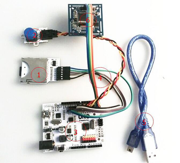
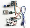
Step 1 Needed tool for testing
Hardware
1. SD Module
2. Digital key module
3. Arduino UNO
4. Jumper wire
5. USB cable
6. VC0706 camera module
Software
1. Camera_VC0706_TEST 2. Arduino IDE(download it from official website)
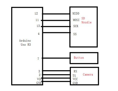
Step 2 Hardware connection
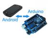
1. Connect the hardware as below
2. Here below is the physical diagram

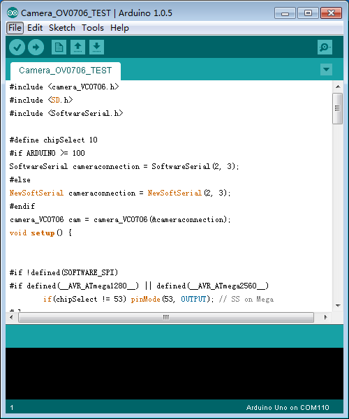
Step 3 Software use and code programming
1. Firstly download the two files of Camera_VC0706_lib and Camera_VC0706_TEST from the Camera Module Code written by ElecFreaks and then unzip it.
2. Put the unzipped file of Camera_VC0706_lib into the Arduino IDE folder of Libraries.
3. Open unzipped file of Camera_VC0706_TEST, and the program the code into UNO. The detailed steps are demonstrated as below.
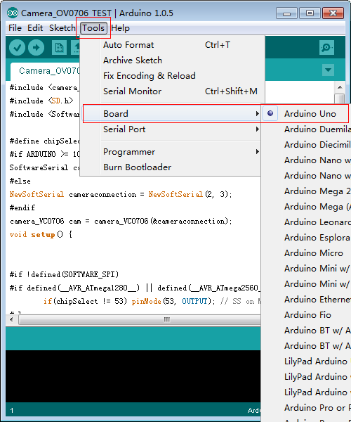
4. Click Tools,and then choose the board of Arduino uno like below
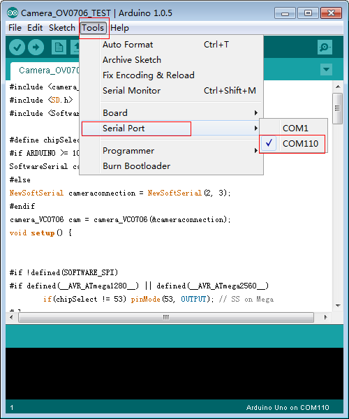
5. Click Tools / Serial Port,and then choose the corresponding COM number.
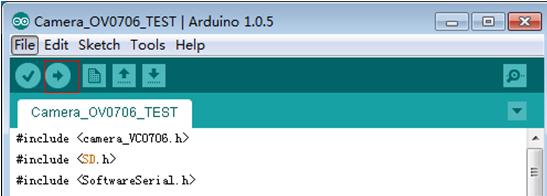
6. And then click the button of programming like below in red rectangle,program the code into the UNO board until done uploading appears.
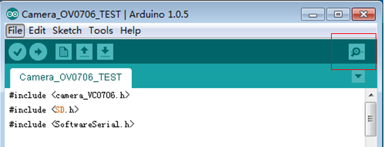
7. Finally open the monitoring serial port as below in red rectangle.
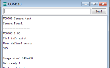
8. When the serial port display the data like demonstrated below, you can press the digital keys to take a photo.
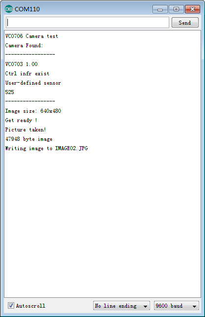
9. If photo was taken successfully, the serial port would be displayed as below
10. Until now, the module testing has been completed.
About the Author


How to Send Micro:bit Data to ThingSpeak IoT Platform
January 11, 2018
VC0706 Camera Module DIY Guide
December 18, 2014

nRF24L01 Module Demo for Arduino
May 6, 2011


Children’s Programming Education is the Future Trend
March 20, 2024

ELECFREAKS AI Smart Lens Now Compatible with Gigo Building Blocks!
February 21, 2024


Comments