Case 03: Trimpot
Contents
5. Case 03: Trimpot#

5.1. Introduction#
A trimpot is an adjustable electronic component. It consists of a resistor body and a rotating or sliding system. When a voltage is applied between the two fixed contacts of the resistor body, the position of the contacts on the resistor body is changed by the turning or sliding system, and a voltage is obtained between the moving contacts and the fixed contacts in relation to the position of the moving contacts. It is mostly used as a voltage divider, in which case the potentiometer is a four-terminal element. In the following lesson we will read the output voltage of the trimpot and display it as a wavy line on the Pico:ed 7 * 17 screen.
5.2. Components List#
Hardware#
1 × Pico:ed
1 × USB Cable
1 × Breadboard Adapter
1 × 83×55mm Breadboard
1 × 10kΩ Resistors
N* Dupont Cables
5.3. Main Components#
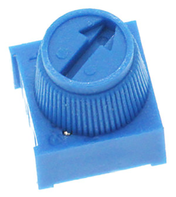
Trimpot#
A trimpot is an adjustable electronic component. It consists of a resistor body and a rotating or sliding system. When a voltage is applied between the two fixed contacts of the resistor body, the position of the contacts on the resistor body is changed by the turning or sliding system, and a voltage is obtained between the moving contacts and the fixed contacts in relation to the position of the moving contacts. It is mostly used as a voltage divider.
5.4. Steps#
Hardware Connection#
Connect the components as the pictures suggest:
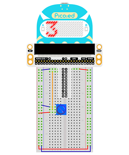
This is the picture after finishing the connection:
Rotate the trimpot and the output voltage will vary among 0V and 3V as the button is rotated.
5.5. Programming#
Program Preparation: Prpgramming environment
Sample Code:#
# Import the modules that we need:
import board
import picoed
import analogio
import time

# Set the connected pins to trimpot
poten = analogio.AnalogIn(board.P0_A0)

# Initialize the data list and save the value of the trimpot, thus we can set the light level of the LEDs screen with them.
data = [0, 0, 0, 0, 0, 0, 0, 0, 0, 0, 0, 0, 0, 0, 0, 0, 0]
for i in range(picoed.display.width):
    data[i] = int(poten.value / 9363)


# Then loop converts the value of the trimpot to the Y coordinate of the LED in the 17th column of the LED screen on the Pico:ed, and scrolls to the left in turn.
while True:

    # Analog value of the pin(0-65535)map to the height of the matrix(0-7)
    data[16] = int(poten.value / 9363)
    for i in range(len(data)):
        picoed.display.pixel(i, data[i] - 1, 0)
        if i != 16:
            data[i] = data[i+1]
        picoed.display.pixel(i, data[i] - 1, 30)
        picoed.display.pixel(16, data[16] - 1, 0)
        time.sleep(0.01)
Details of the Code:#
Import the modules that we need.
boardis the common container, and you can connect the pins you’d like to use through it.picoedmodule is able to set the LED effect on Pico:ed. Thedigitaliomodule contains classes to provide access to basic digital IO.timeis the module contains the fuction of time setting.
import board
import picoed
import analogio
import time
Set the connected pins of the trimpot, here we use P0_A0.
poten = analogio.AnalogIn(board.P0_A0)
If the pins you are using are not P0_A0 and P1_A1, the other pin numbers can be viewed by entering the following code in the shell window below the Thonny editor.
>>> import board
>>> help(board)
object <module 'board'> is of type module
  __name__ -- board
  board_id -- elecfreaks_picoed
  BUZZER_GP0 -- board.BUZZER_GP0
  I2C0_SDA -- board.BUZZER_GP0
  I2C0_SCL -- board.I2C0_SCL
  BUZZER -- board.BUZZER
  BUZZER_GP3 -- board.BUZZER
  P4 -- board.P4
  P5 -- board.P5
  P6 -- board.P6
  P7 -- board.P7
  P8 -- board.P8
  P9 -- board.P9
  P10 -- board.P10
  P11 -- board.P11
  P12 -- board.P12
  P13 -- board.P13
  P14 -- board.P14
  P15 -- board.P15
  P16 -- board.P16
  SDA -- board.SDA
  P20 -- board.SDA
  SCL -- board.SCL
  P19 -- board.SCL
  BUTTON_A -- board.BUTTON_A
  BUTTON_B -- board.BUTTON_B
  SMPS_MODE -- board.SMPS_MODE
  VBUS_SENSE -- board.VBUS_SENSE
  LED -- board.LED
  P0_A0 -- board.P0_A0
  P0 -- board.P0_A0
  A0 -- board.P0_A0
  P1_A1 -- board.P1_A1
  P1 -- board.P1_A1
  A1 -- board.P1_A1
  P2_A2 -- board.P2_A2
  P2 -- board.P2_A2
  A2 -- board.P2_A2
  P3_A3 -- board.P3_A3
  P3 -- board.P3_A3
  A3 -- board.P3_A3
Initialize the data list and save the value of the trimpot, thus we can set the light level of the LEDs screen with them.
data = [0, 0, 0, 0, 0, 0, 0, 0, 0, 0, 0, 0, 0, 0, 0, 0, 0]
for i in range(picoed.display.width):
    data[i] = int(poten.value / 7000)
Then loop converts the value of the trimpot to the Y coordinate of the LED in the 17th column of the LED screen on the Pico:ed, and scrolls to the left in turn.
while True:
    data[16] = int(poten.value / 7000)
    for i in range(len(data)):
        picoed.display.pixel(i, data[i] - 1, 0)
        if i != 16:
            data[i] = data[i+1]
        picoed.display.pixel(i, data[i] - 1, 30)
        picoed.display.pixel(16, data[16] - 1, 0)
        time.sleep(0.01)
5.6. Result#
Rotate the trimpot and the output voltage of the trimpot displays as a wavy line on the Pico:ed 7 * 17 screen.
5.7. Exploration#
If we want to change the light level of the LEDs with the trimpot, how can we design the circuit and program?