Case 06: Self-lock Switch
Contents
8. Case 06: Self-lock Switch#
8.1. Introduction#
A self-locking switch is a common type of push button switch. When we press the switch button for the first time, the switch circuit is connected and remains in this state, i.e. self-locking. When the switch button is pressed again, the switch is disconnected and the switch button pops out at the same time. In this lesson, we will use a self-lock switch to control the lighting and turning off of an LED.
8.2. Components List#
Hardware#
1 × Pico:ed
1 × USB Cable
1 × Breadboard Adapter
1 × 83×55mm Breadboard
1x Self-lock Switch
1× LED
3 × 100Ω Resistors
N* Dupont Cables
8.3. Main Components#
Self-lock Switch#
A self-lock switch generally means that the switch comes with a mechanical locking function, so that when you press it, the button will not fully jump up after you release it, it is in a locked state and needs to be pressed again before it is unlocked to fully jump up. It is then called a self-lock switch. This is the type of switch used in the early days of direct powering televisions and monitors.
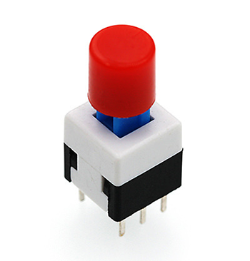
Note: This self-lock switch contains two sets of knife double-throw switches, only one of which was used in this test, the common pin of one of the sets was cut off.
8.4. Steps#
Hardware Connection#
Connect the components as the pictures suggest:
Connect the self-lock switch to the P0 port of the breakout board
Connect the led to the P2 port of the breakout board via a 100Ω resistor
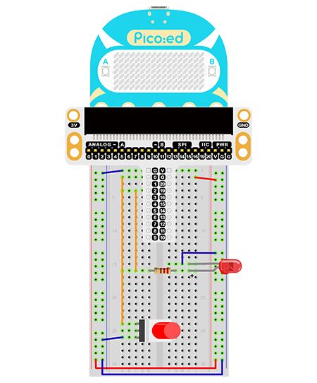
This is the picture after finishing the connections:
8.5. Programming#
Program Preparation: Prpgramming environment
Sample Code:#
# Import the modules that we need:
import board
import digitalio

# Set the connected pins and directions of the LED.
led = digitalio.DigitalInOut(board.P2_A2)
led.direction = digitalio.Direction.OUTPUT

# Set the connected pins and directions of the self lock switch.
locking = digitalio.DigitalInOut(board.P0_A0)
locking.direction = digitalio.Direction.INPUT

# Control the LED with the self lock switch.
while True:
    led.value = locking.value
Details of the Code:#
Import the modules that we need.
boardis the common container, and you can connect the pins you’d like to use through it. Thedigitaliomodule contains classes to provide access to basic digital IO.
import board
import digitalio
Set the pins and directions of the breadboard adapter connecting to the LEDs
led = digitalio.DigitalInOut(board.P2_A2)
led.direction = digitalio.Direction.OUTPUT
Set the pins of the adapter for connecting self-lock switch
locking = digitalio.DigitalInOut(board.P0_A0)
locking.direction = digitalio.Direction.INPUT
If the pins you are using are not P0_A0 and P1_A1, the other pin numbers can be viewed by entering the following code in the shell window below the Thonny editor.
>>> import board
>>> help(board)
object <module 'board'> is of type module
  __name__ -- board
  board_id -- elecfreaks_picoed
  BUZZER_GP0 -- board.BUZZER_GP0
  I2C0_SDA -- board.BUZZER_GP0
  I2C0_SCL -- board.I2C0_SCL
  BUZZER -- board.BUZZER
  BUZZER_GP3 -- board.BUZZER
  P4 -- board.P4
  P5 -- board.P5
  P6 -- board.P6
  P7 -- board.P7
  P8 -- board.P8
  P9 -- board.P9
  P10 -- board.P10
  P11 -- board.P11
  P12 -- board.P12
  P13 -- board.P13
  P14 -- board.P14
  P15 -- board.P15
  P16 -- board.P16
  SDA -- board.SDA
  P20 -- board.SDA
  SCL -- board.SCL
  P19 -- board.SCL
  BUTTON_A -- board.BUTTON_A
  BUTTON_B -- board.BUTTON_B
  SMPS_MODE -- board.SMPS_MODE
  VBUS_SENSE -- board.VBUS_SENSE
  LED -- board.LED
  P0_A0 -- board.P0_A0
  P0 -- board.P0_A0
  A0 -- board.P0_A0
  P1_A1 -- board.P1_A1
  P1 -- board.P1_A1
  A1 -- board.P1_A1
  P2_A2 -- board.P2_A2
  P2 -- board.P2_A2
  A2 -- board.P2_A2
  P3_A3 -- board.P3_A3
  P3 -- board.P3_A3
  A3 -- board.P3_A3
While true, set the state of the LED light to the state of the self-lock push button switch.
while True:
    led.value = locking.value
8.6. Result#
Press the button once to light the LED on and press again to light it off.
8.7. Exploration#
How to use two self-lock switches to realize the function of the stair light?