


Micro:bit Experiment 09:Buzzer —???Elecfreaks Mirco: bit Starter Kit Course

Introduction
Buzzer is a kind of electronic sound receiver with integrated structure. It is widely used as a voice device in electronic products like computers, printers, copying machines, alarm apparatus, electronic toys, auto electronic devices, telephones, etc..In this experiment, we are going to use Micro:bit to drive buzzer and make its sound circulate between high frequency and low frequency just like alarm song. And we will present its sound frequency on Micro:bit screen with bar chart format.
Component List
Hardware:
1 x Micro:bit Board
1 x Micro-B USB Cable
1 x Microbit Breadboard Adapter
1 x Transparent Breadboard - 83 * 55 mm
1 x Mini Speaker (Buzzer)
1 x TIP 120 NPN Transistor
1 x 100 Ohm Resistors
1 x Breadborad jumper wire 65pcs pack
Tips: If you want all components above, you will need Elecfreaks Micro:bit Starter Kit.
Software:
Microsoft Makecode Online Editor
Major Component Introduction
Buzzer
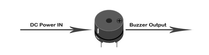
Buzzer is a kind of voice device. It is made of vibration device and resonance device. According to the difference of control method, we can divide buzzer into active type and passive type. 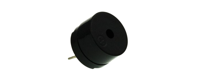 Here's the working principle of active buzzer: Because active buzzer has integrated amplify sampling circuit and resonance system, when DC power input pass through active buzzer, it will make resonance device generate sound signal. We can see the schematic diagram below for the working principle of active buzzer:
The working principle of passive buzzer is: When square wave signal pass through the buzzer, its resonance device will transform the square wave signal input into sound signal output. Below is the schematic diagram for the working principle of passive buzzer:
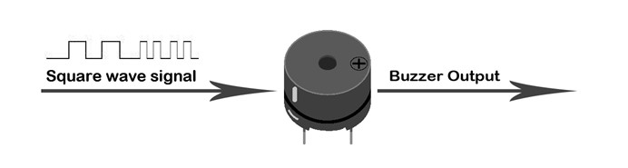
Note: In this experiment, we use passive buzzer only.
Transistor
Transistor is a kind of semi-conductor component for current control. It is used to amplify the weak signal to signal with larger frequency.  If we input PWM signal produced by Micro:bit into buzzer directly, the buzzer will send out feeble voice. This is because the drive current of I/O port is usually too weak to directly drive components like buzzer. At this time, we have to use transistor to amplify the current of PMW signal so that the buzzer can alarm properly. Here is the circuit diagram for a typical application of using transistor to drive buzzer:
  Hardware Connection:
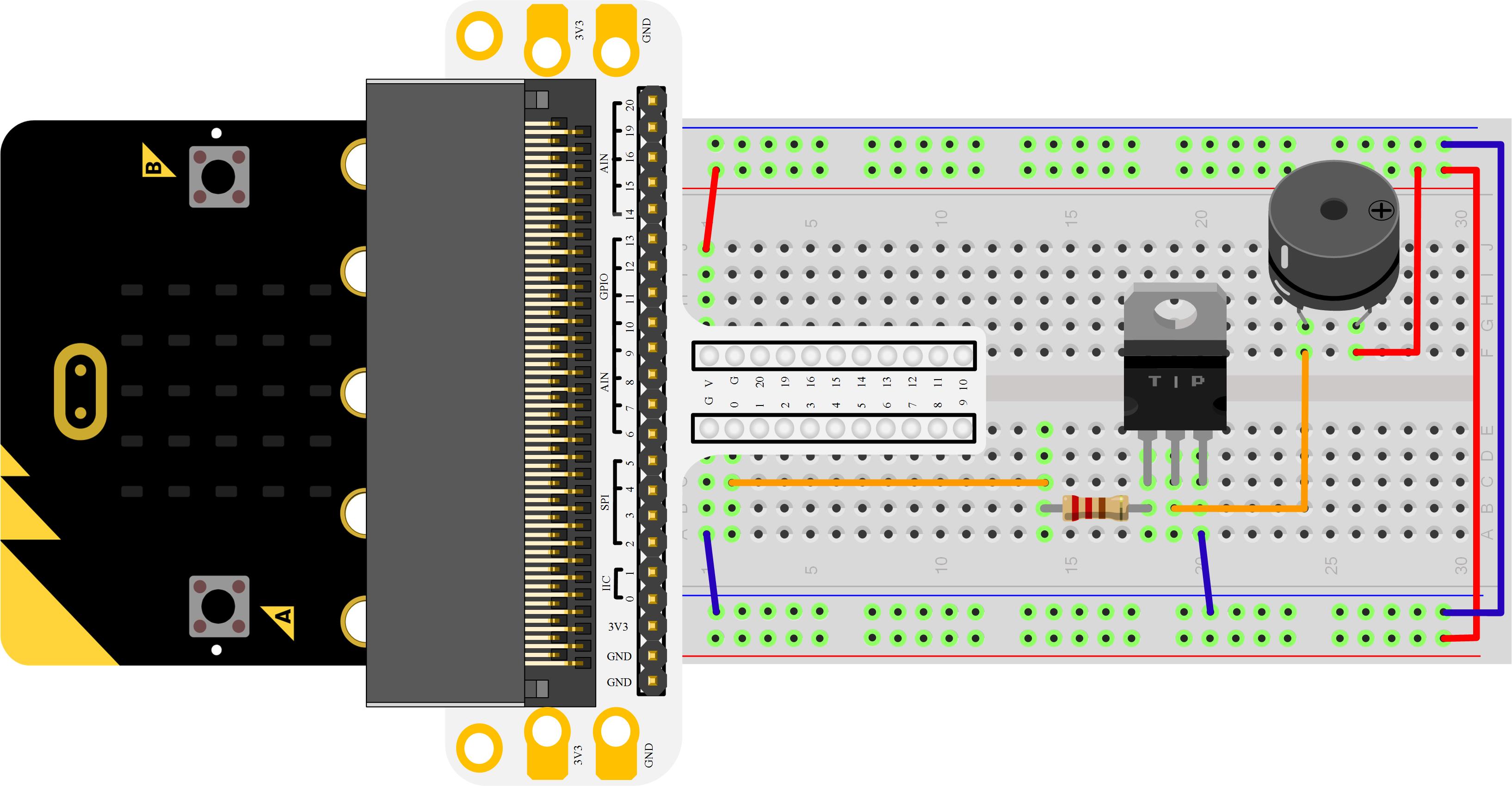
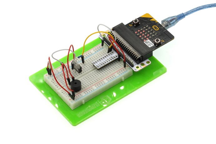
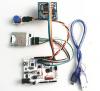
Please complete connection according to the picture below.

After connection, you will see:
Programming
Please open Microsoft Makecode, write your code in the edit area. I would like to suggest you to program by yourself first. Of course, you can see the whole program in the link below. Just click "Edit" on the right top corner of the interface to edit your program, and then click "Download" to download your code into Micro:bit directly.
Code Explanation
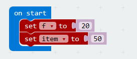
Analog Set Period Configure the period of Pulse Width Modulation (PWM) on the specified analog pin. Before you call this function, you should set the specified pin as analog. Under brick "on start", set two variables: variable "f" is for audio frequency, variable "item" for frequency change intervals.
Under brick "forever", "analog write pin P0 to 512" indicates to make "P0" output square wave.

Variable "T" is for square wave period. We all know that " period=1s/frequency" and time unit in "Analog Set Period" is "us". So we get "T=1000000/f".

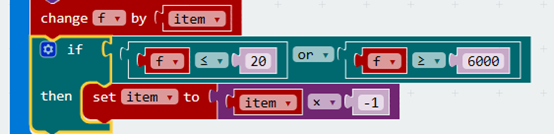
Every circulation makes "f" change "item", "f" changes among 20Hz to 6000Hz.
Experiment Result
The sound sent out by buzzer changes between high frequency and low frequency. And we can see the bar chart of frequency on Micro:bit screen. 
Question
If we want to make a high temperature alarming device with temperature sensor and buzzer, then how can we design circuit and program? We look forward to your feedback and further discussion.
Relative Readings:
Start Your Micro:bit Programming Trip Micro:bit Experiment 01: LED Scroller —— Elecfreaks Micro:bit Starter Kit Course Micro:bit Experiment 02: Button —— Elecfreaks Mirco:bit Starter Kit Course Micro:bit Experiment 03: Trimpot —— Elecfreaks Mirco:bit Starter Kit Course Micro:bit Experiment 04: Photocell —— Elecfreaks Mirco:bit Starter Kit Course Micro:bit Experiment 05: RGB LED —— Elecfreaks Mirco:bit Starter Kit Course Micro:bit Experiment 06: Self-lock Switch —— Elecfreaks Mirco:bit Starter Kit Course Micro:bit Experiment 07:Temperature Sensor —— Elecfreaks Mirco: bit Starter Kit Course Micro:bit Experiment 08:Servo —— Elecfreaks Mirco: bit Starter Kit Course
If you want to read the latest elecfreaks, welcome to like our Facebook PAGE.
About the Author


How to Send Micro:bit Data to ThingSpeak IoT Platform
January 11, 2018
VC0706 Camera Module DIY Guide
December 18, 2014

nRF24L01 Module Demo for Arduino
May 6, 2011


Children’s Programming Education is the Future Trend
March 20, 2024


ELECFREAKS AI Smart Lens Now Compatible with Gigo Building Blocks!
February 21, 2024


Comments