


NRF24L01 with Arduinio's SPI Library

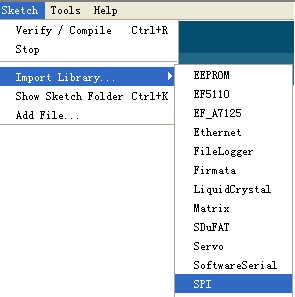
Hi Guys, We have received some mails for asking if we will provide the nRF24L01's hardware SPI demo or library, which we just provided the software SPI before. So we modified the code used SPI library which you can get from Arduino's standard library.

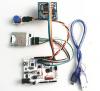
The frist change is the connection between pins and Arduino. The old mode is: GND – GND, VCC – 3.3V, CS – D8, CSN – D9, SCK – D10, MOSI – D11, MISO – D12, IRQ – D13 If you want to use Arduino's SPI library, you should connect them as below: GND – GND, VCC – 3.3V, CS – D8, CSN – D9, SCK – D13, MOSI – D11, MISO – D12, IRQ – D10Define about CS, IRQ and CSN could be changed by yourself, the other pins you can not change because of the Arduino's board provide. The second, let us show you where the code was changed, it was very easy. Main modefied is :
[cce_cpp]
unsigned char SPI_RW(unsigned char Byte)
{
  unsigned char i;
  for(i=0;i<8;i++)                      // output 8-bit
  {
    if(Byte&0x80)
    {
      SPI_PORT |=MOSI;                  // output 'unsigned char', MSB to MOSI
    }
    else
    {
      SPI_PORT &=~MOSI;
    }
    SPI_PORT|=SCK;                      // Set SCK high..
    Byte <<= 1;                         // shift next bit into MSB..
    if(SPI_IN & MISO)
    {
      Byte |= 1;                        // capture current MISO bit
    }
    SPI_PORT&=~SCK;                     // ..then set SCK low again
  }
  return(Byte);                         // return read unsigned char
}
[/cce_cpp]
to
[cce_cpp]
unsigned char SPI_RW(unsigned char Byte)
{
  return SPI.transfer(Byte);
}
[/cce_cpp]
Oh, So clear. At last, maybe you like this code mode, however there are some defects also, it's just for Arduino but other microprocessors. The softwore SPI is more in common use other development platform. OK, this just is a sample code for your reference. Download the Full Code.. (include SPI_rf24L01_TX and SPI_rf24L01_RX) Link to nRF24L01_Demo_For_Arduino.. (software SPI mode)
About the Author


How to Send Micro:bit Data to ThingSpeak IoT Platform
January 11, 2018
VC0706 Camera Module DIY Guide
December 18, 2014

nRF24L01 Module Demo for Arduino
May 6, 2011


Children’s Programming Education is the Future Trend
March 20, 2024


ELECFREAKS AI Smart Lens Now Compatible with Gigo Building Blocks!
February 21, 2024


Comments