


Bluetooth Modem Video Tutorials

Besides Bluetooth Shield and Bluetooth Bee video tutorials, currently we continue to release Bluetooth series product - Bluetooth Modem Video Tutorials. Bluetooth has increasingly become the focused topic in ordinary life, and is always our important and hot-sale product, therefore, we really hope these tutorials would do something for our customers in the real DIY operation. You can also download the Bluetooth Modem User-Guide besides watch Bluetooth Modem video.
Bluetooth Modem Introduction
The Bluetooth Modem is the latest Bluetooth wireless serial cable! This version of the popular Bluetooth uses the HC-05/HC-06 module. These modems work as a serial (RX/TX) pipe. Any serial stream from 9600 to 115200bps can be passed seamlessly from your computer to your target. The Power Supply Voltage is 3.3V-5V and the IO Voltage is 3.3V/TTL The remote unit can be powered from 3.3V up to 6V for easy battery attachment. All signal pins on the remote unit are 3V-6V tolerant. No level shifting is required. Do not attach this device directly to a serial port. You will need an RS232 to TTL converter circuit if you need to attach this to a computer. You can either solder a 6-pin header or individual wires.
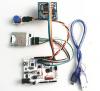
Hardware and Software Preparation

Part 1 Communication Between Bluetooth Modem and Bee Adapter

1. Set the Bee Adapter Switch in H Port to enter AT Mode
2. Set to IO Voltage 3V3
3. Assemble the Bee Adapter and Bluetooth Modem with Jumper Wire, and then connect to PC (make sure Bluetooth Modem LED blink slowly in AT Mode)

- KEY connect to KEY
- VCC connect to VCC
- GND connect to GND
- TX connect to RX
- RX connect to TX
4. Open Serial Tool sscom32 and set the BaudRate as 38400. Type AT, and it would respond OK. With Bee Adapter, you can achieve AT Command control not need of programming code.
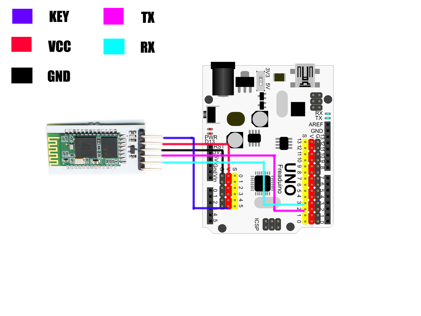
Part 2 Communication Between Bluetooth Modem and Arduino

- Set to IO Voltage 3V3, and make sure Bluetooth Modem LED blink slowly in AT Mode.
- Connect Bluetooth and UNO with jumper wire as below, and then link to PC

- Bluetooth KEY link to UNO V(VCC), so as to enter AT Mode .
- Bluetooth VCC to UNO V( VCC)
- Bluetooth GND to UNO G(GND)
- Bluetooth TX to UNO D2
- Bluetooth RX to UNO D3
Step 1. Achieve Manually AT Command Control
1. Open the Arduino IDE 1.0.X, and copy the code from Elecfreaks wiki to it.
2. Import library of SoftwareSerial, because library of NewSoftSerial is just suitable of edition before ArduinoIDE 1.0, such as IDE0022, IDE0023.
3. Delete the library of NewSoftSerial and modify the NewSoftSerial into SoftwareSerial.
4. Download TimerOne from http://code.google.com/p/arduino-timerone/downloads/list
5.Compiling sketch until Done compiling appears
6.Upload code until Done uploading appears
7.Open sscom32 and set BaudRate as 38400
8.Manually input AT and it would respond OK
9. Input AT+ROLE? And it would respond +ROLE=0, therefore, We default the Bluetooth Modem as SLAVE Mode
10.Input AT+ROLE=1, we can set it as Master Mode
11.Input AT+ROLE=0, we can set it back as SLAVE Mode
Step 2. Achieve Automatically AT Command Control
1. Modify the code (Remove // before Timer1)and then upload it again in Arduino IDE 1.0.X
2. The Serial Monitor can automatically respond OK for AT Command
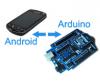
Part 3. Communication Between Android and Arduino with Bluetooth
- Remove the KEY PIN jumper wire to enter Communication Mode. In Communication Mode, make sure the Bluetooth Modem LED blink quickly. If necessary, re-plug the USB Cable.
- Modify the code (add // before Timer1, especially replace the BaudRate from 38400 to 9600 ), and then upload the code again.
Step 1. Android Installation
1. Download APP for EF _BluetoothBeeV1.1 from http://elecfreaks.com/store/download/datasheet/Bluetooth/EF_BluetoothBeeV1.1.zip
2. Install the APK file to your Android phone.

Step 2. Android Communication
- Click the icon of ElecFreaks BluetoothBee as above and then open Bluetooth.
- Click As Client and start scanning
- When it scan out HC-05, click HC-05.
- Type the Bluetooth pairing PIN 1234.
- Input hello,elecfreaks in mobile, and the Serial Tool sscom32 would display hello,elecfreaks from mobile. (For sscom32, remember to set the BaudRate as 9600.)
- Input hello from PC, mobile would also respond hello.

Q&A
If you use Arduino Mega1280/2560 or Freaduino ADK there are some difference. Please note the NewSoftSerial library about Mega2560 explanation in SoftwareSerial.cpp :[cce] // Specifically for the Arduino Mega 2560 (or 1280 on the original Arduino Mega) // majority of the pins are NOT PCINTs, SO BE WARNED (i.e. you cannot use them as receive pins) // Only pins available for RECEIVE (TRANSMIT can be on any pin): // (I've deliberately left out pin mapping to the Hardware USARTs - seems senseless to me) // Pins: 10, 11, 12, 13, 50, 51, 52, 53, 62, 63, 64, 65, 66, 67, 68, 69 [/cce]That means the library do not support D0-D7 as receiving pins, and you just could use pins:10, 11, 12, 13, 50, 51, 52, 53, 62, 63, 64, 65, 66, 67, 68, 69 for receiving. So there are two way to resolve it, but they all need external jumper wires. First method: Change the define of rxPin and txPin. Jumper wires connect to DOUT-D10, DIN-D11.
[cce]
#define rxPin 10
#define txPin 11
[/cce]
Second method: Use the other Hardware Serial port because Mega has 4 hardware serial ports. Jumper wires connect to DOUT-RX1(D19) DIN-TX1(D18)
About the Author


How to Send Micro:bit Data to ThingSpeak IoT Platform
January 11, 2018
VC0706 Camera Module DIY Guide
December 18, 2014

nRF24L01 Module Demo for Arduino
May 6, 2011


Children’s Programming Education is the Future Trend
March 20, 2024


ELECFREAKS AI Smart Lens Now Compatible with Gigo Building Blocks!
February 21, 2024


Comments