


Micro:bit Experiment 04: Photocell ???Elecfreaks Mirco: bit Starter Kit Course

Introduction
Photocell is a kind of special resistance based on internal photoelectric effect. Its resistant value is opposite to the brightness of light. Brighter light leads to lower resistant value. Usually photocell is the core component of a photoswitch. In the following experiment, we are going to use photocell to control the brightness of 5*5 LED screen on Micro:bit.
Component List
Hardware:
1 x Micro:bit Board
1 x Micro-B USB Cable
1 x Microbit Breadboard Adapter
1 x Transparent Breadboard - 83 * 55 mm
1 x Photocell
1 x 10k Ohm Resistors
1 x Breadborad jumper wire 65pcs pack
Tips: If you want to buy all components above, then you will need Elecfreaks Micro:bit Starter Kit.
Software:
Microsoft Makecode Online Editor
Introduction of Major Components
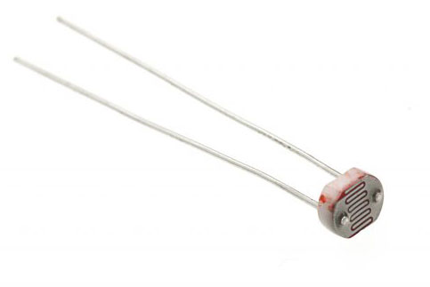
Photocell
Photocell is a kind of special resistance made of semi-conductor materials like Cds or CdSe. It is based on internal photoelectric effect. Brighter light, lower resistant value. As with the increase intensity of light, its resistant value swiftly decreased. The minimum light resistant value can reach under 1K??? Photocell is very sensitive to light. When there is no light, its resistant value arrives maximum. Its dark resistant value usually can reach 1.5M???at max.
Hardware Connection
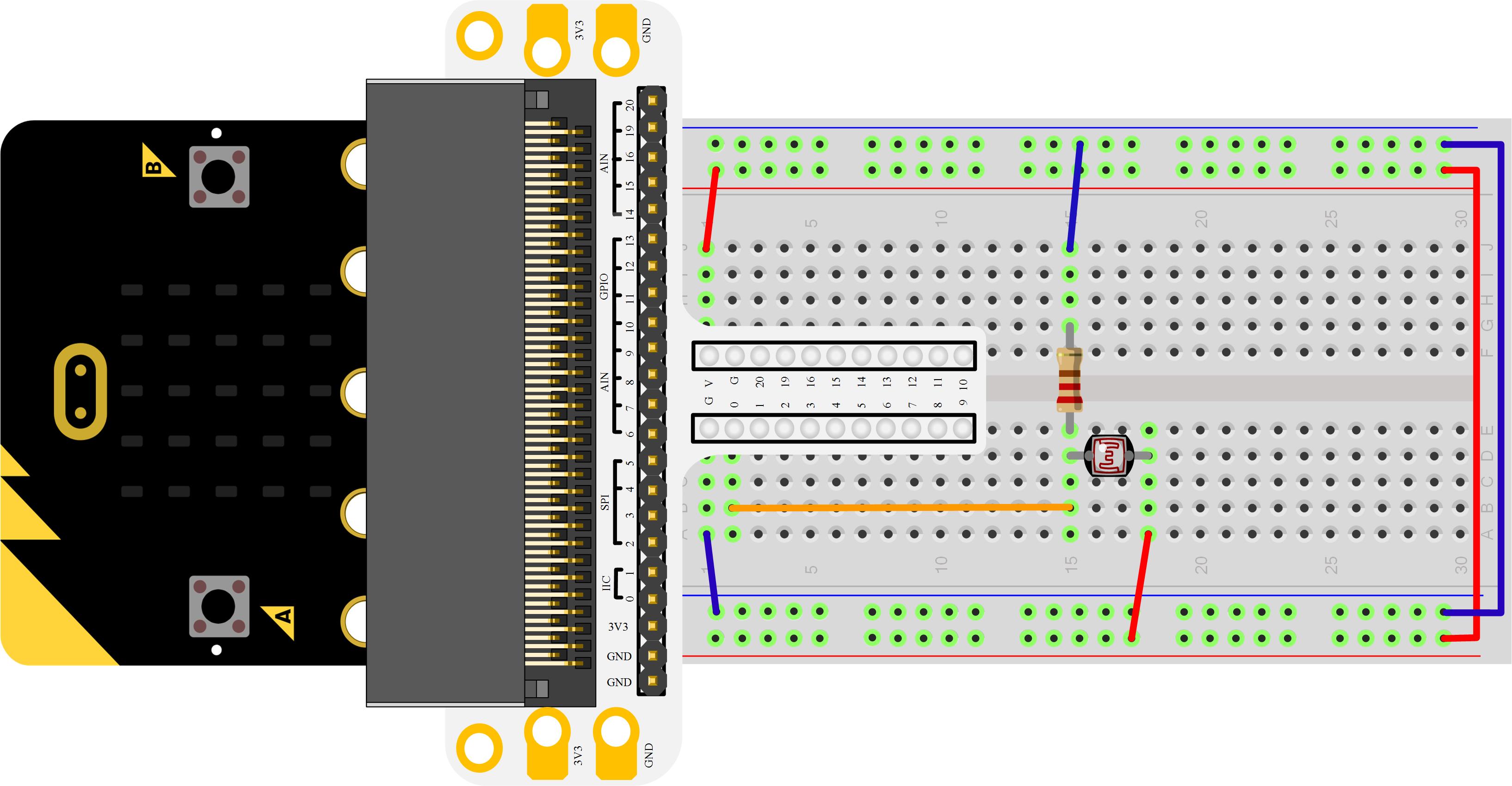
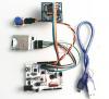
Please complete hardware connection according to the picture below.

A bleeder circuit will be formed when photocell and 10K???resistance connect inserial.
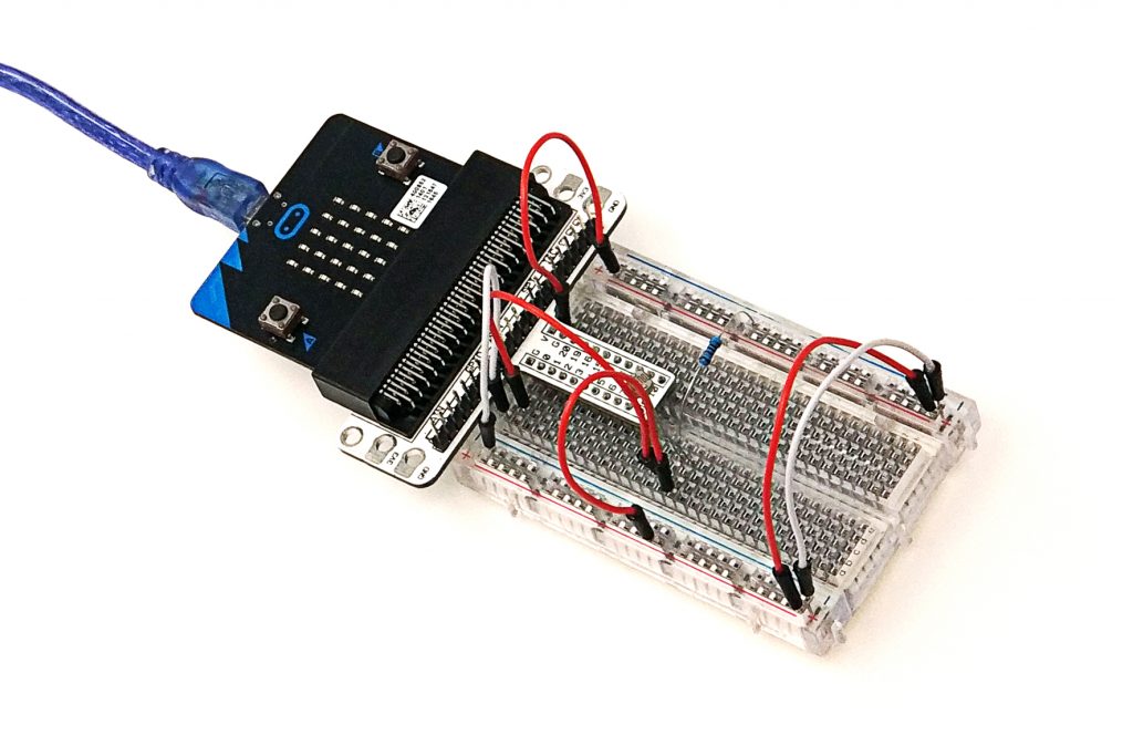
After connection, you can see:
Programming
Open Microsoft Makecode, write code in editor window. I would like to suggest you to try programming by yourself first.
Of course, you can see the whole program in the link below. Just click “Edit” on the right top corner, then click “download” to download the whole code into Micro:bit.
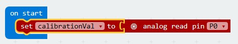
This is assignment operation. set a to 1 equals to “a=1”. We use an equals sign to make a variable store the number or string you say.
When you use the equals sign to store something in a variable, the equals sign is called an assignment operator, and what you store is called a value.
analog read
Read an analog signal (0 through 1023) from the pin you say.
show icon
Shows the selected icon on the LED screen.
Clear Screen
Turn off all the LED lights on the LED screen.
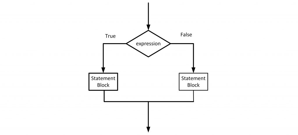
If else
In “ Experiment 02 ”, we have talked about the usage of “if” sentence. In sentence of “ if else”, when the format value is false(or 0), then it will implement “else” brick program before running program in sequence. Here is the flow chart:
In this experiment, Micro:bit read analog voltage of Pin0 port as the reference value of brightness.
In brick “ forever” , scan analog voltage of Pin0 in circulation. Once the voltage lower than reference value minus 2( it shows intensity of light increase, resistant value of photocell decrease), then it tells the light has been turned off.
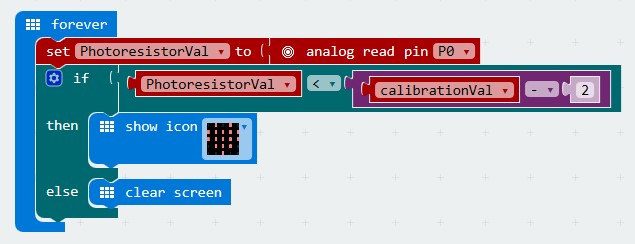
In program, calibrationVal-2 is for adjusting sensitivity. Lower value, higher sensitivity. However, it is not suitable for all kinds of light environment. You have to adjust this parameter until it can adapt to the present light condition.
Experiment Result
Turn on light, 5*5 LED screen on Micro:bit become empty. Turn off light, LED screen displays a sign of heart.
Note:
After resetting Micro:bit, it will calibrate the reference value according to the present brightness. So, in order to make the program run properly, we must start Micro:bit program on the condition that the light is turned on .
Question:
If we want to use photocell to control a LED bead, then how to design circuit and program? We look forward to your further discussions or comments.
Relative Readings:
Start Your Micro:bit Programming Trip
Micro:bit Experiment 01: LED Scroller —— Elecfreaks Mirco: bit Starter Kit Course
Micro:bit Experiment 02: Button —— Elecfreaks Mirco: bit Starter Kit Course
Micro:bit Experiment 03: Trimpot —— Elecfreaks Mirco: bit Starter Kit Course
About the Author


How to Send Micro:bit Data to ThingSpeak IoT Platform
January 11, 2018
VC0706 Camera Module DIY Guide
December 18, 2014

nRF24L01 Module Demo for Arduino
May 6, 2011


Children’s Programming Education is the Future Trend
March 20, 2024

ELECFREAKS AI Smart Lens Now Compatible with Gigo Building Blocks!
February 21, 2024


Comments