

Elecfreaks Motor:bit User Guide

Introduction
ELECFREKAS Motor:bit is a kind of motor drive board based on micro:bit. It has integrated a motor drive chip TB6612, which can drive two DC motors with 1.2A max single channel current. Motor:bit has integrated Octopus series' sensor connectors. You can plug various sensors into it directly. Among these connectors, P0, P3-P7, P9-P10 support sensors with 3.3V power voltage only; P13-P16, P19-P20 support 3.3V or 5V sensors. You can change electric level by sliding the switch on the board. 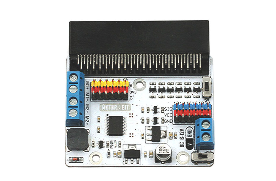 Hardware Features:
-
Motor Drive Chip: TB6612
-
Support GVS-Octopus electric Bricks' connector
-
Some GVS connectors support electric level switch between 3.3V and 5V.
-
With 2 channels DC motor connectors, max single channel current is 1.2A.
-
Input Voltage: DC 6-12V
-
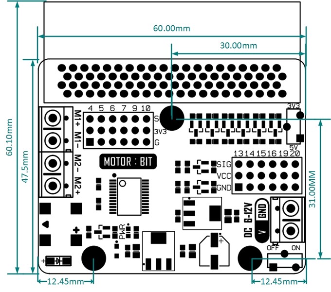
Dimension: 60.00mm X 60.10mm
-
Weight: 30 g
Application:
-
It is compatible with ElecFreaks Octopus electric bricks module series due to its built-in 3 pin IO electric brick GVS extension connector.
-
It can be used as the development board of mini smart cars and balance cars.
-
Users can develop mobile-controlled robot, robot arms, etc..
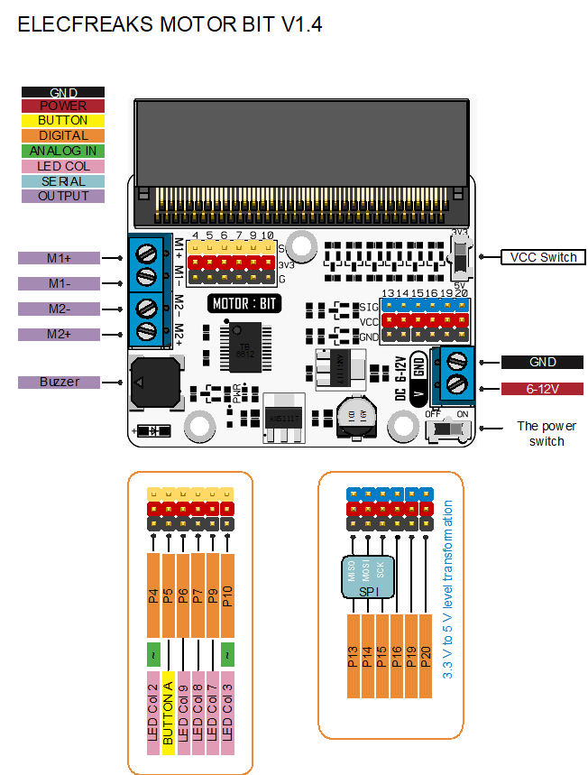
Connector Information:
| Type |
Instruction |
| Buzzer | Buzzer is controlled by P0. |
| LED COL | Micro:bit LED matrix control pin |
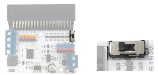
| VCC Switch | 3.3V/5V electric level switch only for P13-P16, P19, P20. |
| Button-A | Micro:bit main board button A |
| P4-P7,P9,P10,P13-P16,P19,P20 | Digital connecotr |
| P4,P10 | Analog connector/PWM |
| SCK MISO MOSI | Hardware SPI pin -P13,P14,P15 |
| SDA SCL | Hardware IIC pin -P19,P20 |
| The power switch | External power switch |
| 6-12V GND | External power connector |
| M1+ M1- M2+ M2- | Connector of two DC motor |
| PWR | Power Indicator |
Detailed Introduction Of Some Connectors???/span>
1. VCC Switch-3.3V/5V electric level switch. Slide switch to the end of 5V, the electric level of the blue pins (P13???/span>P14???/span>P15???/span>P16???/span>P19???/span>P20) on motor:bit is 5V, and the voltage of the red power pins is 5V too. Similarly, when slide switch to 3.3V, the voltage of blue pins and red pins are 3.3V.
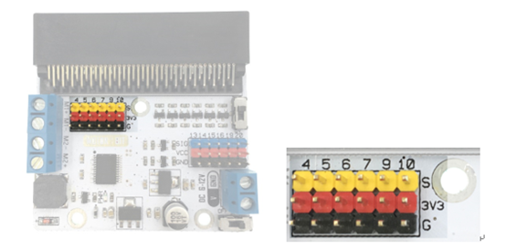
2. Digital Pin Connector.
Digital pins: P4???/span>P5???/span>P6???/span>P7???/span>P9???/span>P10.
G-3V3-S connector: 3V3 stands for 3.3V power voltage, G is for GND, S is for signal. GVS is a standard sensor connector, which enables you to plug onto servos and various sensors conveniently. At the same time, it supports our Octopus Bricks series'products.
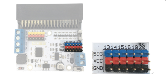
3. 3.3V/5V dual electric level GND-VCC-SIG connector???/span>P13, P14, P15, P16, P19, P20.
The specialty of G-VCC-SIG connector lies in that it can support 3.3V or 5V power device by shifting electric level of 3.3V/ 5V through VCC connector. At the same time, it supports our Octopus Bricks series' products.
Motor Input Connector: Two motor input connectors in total. M1+, M1- and M2+, M2- separately controls a channel of DC motor.
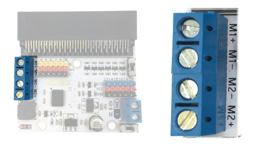
M1???/span>M2 Motor Control Instruction: P8 and P12 relatively controls the rotating direction of M1 and M2; P1 and P2 control motor speed.
-
Pin
Function
Note
P8
Direction control of M1 Positive rotate under high voltage; negative rotate under low voltage. P1
Speed control of M1 PWM P2
Speed control of M2 PWM P12
Direction control of M2 Positive rotate under high voltage; negative rotate under low voltage. Dimension:
Example
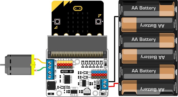
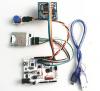
Hardware Connection
Please connect components according to the picture below:
 ProgrammingPositive Rotation Of Motor:
P8 in high electric level means the positive rotation of motor. You can adjust the logic value of P1 to control motor speed. Negative Rotation Of Motor: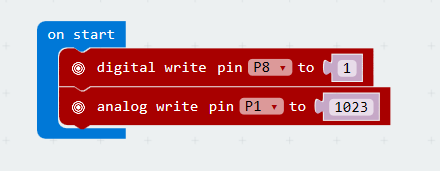
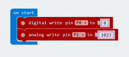
P8 in low voltage level means the negative rotation of motor. ou can adjust the logic value of P1 to control motor speed.
If you need more cases about micro:bit, please keep watching our blogs
Relative Cases:
About the Author


How to Send Micro:bit Data to ThingSpeak IoT Platform
January 11, 2018
VC0706 Camera Module DIY Guide
December 18, 2014

nRF24L01 Module Demo for Arduino
May 6, 2011


Children’s Programming Education is the Future Trend
March 20, 2024


ELECFREAKS AI Smart Lens Now Compatible with Gigo Building Blocks!
February 21, 2024


Comments