

How to Use Breadboard


Breadboard is the most basic component for studying how to build a circuit. In the following article, i am going to show you some knowledge about breadboard.
What is Breadboard?
Breadboard seems very delicious for its name called. However, if you take it into a kind of delicacy, then you are wrong.

Actually, breadboard is a kind of tool designed for none-soldering experiment. There are a lot of small holes on it just like holes on bread. That is why it is called Breadboard.
Why we use Breadboard?
Let's try to think about a question: What shall we do when we want to turn an electric drawing into reality?
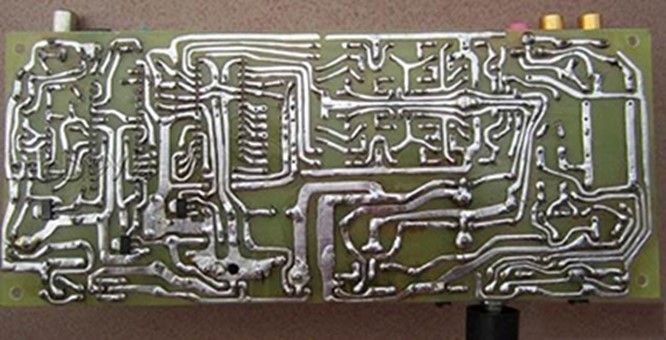
We can solder on PCB board by hand. Suppose if we often disassemble circuit, then we have to solder PCB board one by one. This is time-consuming and it is not easy to reuse the electronic components again. If we have breadboard, then it is much more convenient. We can plug in or out all kinds of electronic components easily according to our requirements. You don't have to solder. This saves a lot of time in circuit assembling and the components can be reused again. So it is suitable for electronic assembling, debugging, and training.
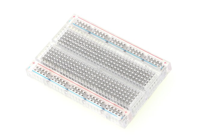
Category of Breadboard None-soldered Breadboard
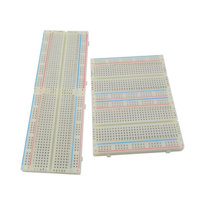
None-soldered Breadboard (see picture below) is motherboard not used for base. It has no power connector for leading out but it can extend a single Breadboard plate. Before using it, you should plug in power supply. You have to plug the two polarities of the power supply into the left and right side plug holes separately. Then, you can plug electronic components to do experiments (before plug electronic components, you have to cut off power supply). When there are more than 5 components to be plugged or not enough plug holes, we need breadboard and connecting wires to connect multiple groups of plug holes.
None-soldered Breadboard is the most common breadboard in circuit experiment. It has several specifications for option.
Single Breadboard
Single Breadboard (see picture below) has motherboard as its base and with specified binding post for power supply connection. Even there are some breadboards used for high voltage experiment that have ground binding posts. This kind of Breadboard is easy to use. You have to connect power supply directly into binding post, then plug in components to do experiment.You have to cut off power supply when plugging into components. If there are more than 5 components to be plugged or not enough plug holes, you have to use Breadboard and wires to connect them. The advantages of Single Breadboard are small volume, portable and convenient to connect or disconnect power supply while the shortcoming is small area, which is not suitable for big-scale analog circuit experiment.
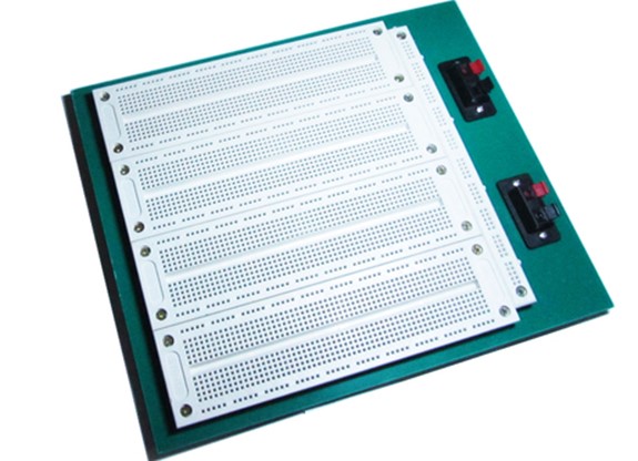
Group Breadboard
Group Breadboard (see picture below) by name is to put a lot of None-soldered Breadboard together and form a new Breadboard. Usually, we fix 2-4 None-soldered Breadboard onto the mother board. Then we use copper foil to connect power cables within mother board together. In professional breadboard group, breadboard is specially designed independent power control for different circuit units so that every board can carry different voltages according to users' demands. Usage of Group Breadboard is same with Single Breadboard. The advantages of Group Breadboard are convenient to connect or disconnect power supply, big area, can do big-scale experiment, high activity and wide application while the shortcomings are big volume, too heavy to carry. It is suitable for experiment or electronic fans to use.
Internal Connection of Breadboard
On breadboard, 5 holes in vertical line are internal connected as a group. Groups between are not connected.
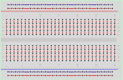
(Circuit is connected in wire connected part)
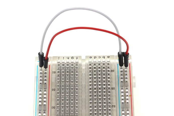
Power port is horizontally connected. Usually red is for positive polar, blue or black is for negative polar. We have to notice, which is very important, power supplies in two sides are not connected. So if you want to use the same power supply of the two side, you have to use a jumper wire to connect both side.
DIP Support
Earlier we mentioned the ravine that isolates the two sides of a breadboard. This ravine serves a very important purpose. Many integrated circuits, often referred to as ICs or, simply, chips, are manufactured specifically to fit onto breadboards. In order to minimize the amount of space they take up on the breadboard, they come in what is known as a Dual in-line Package, or DIP. These DIP chips have legs that come out of both sides and fit perfectly over that ravine. Since each leg on the IC is unique, we don't want both sides to be connected to each other. That is where the separation in the middle of the board comes in handy. Thus, we can connect components to each side of the IC without interfering with the functionality of the leg on the opposite side.
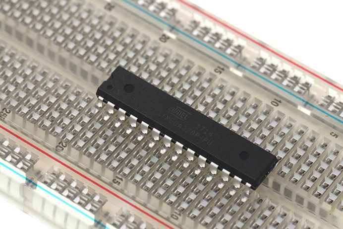
ATmega328 Micro-controller
Rows and Columns
You may have noticed that many breadboards have numbers and letters marked on various rows and columns. These don't serve any purpose other than to help guide you when building your circuit. Circuits can get complicated quickly, and all it takes is one misplaced leg of a component to make the entire circuit malfunction or not work at all. If you know the row number of the connection you are trying to make, it makes it much simpler to plug a wire into that number rather than eyeballing it.
How to Supply Power to Breadboard?
1. Connect outer power supply to positive or negative polarity by jumper wire.
If you are using development board like Micro:bit, then you can use Micro:bit Breadboard Adapter to connect power supply easily. Micro:bit Breadboard Adapter has several power supply and ground footers. You can connect it to power rail or other line on breadboard. Micro:bit usually obtain outer power supply from USB port on computer and battery group. 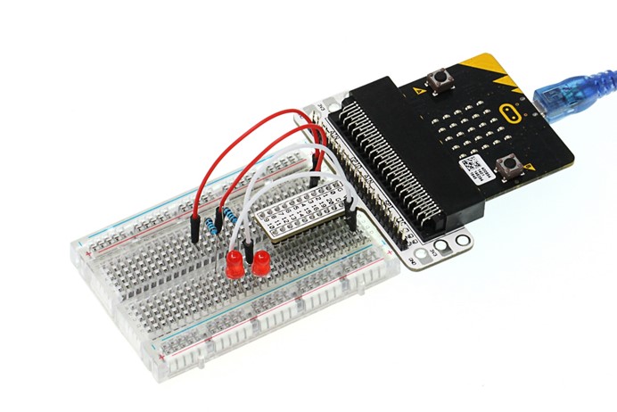 Connect ground (GND) footer from Micro:bit to one line of mini breadboard. Then connect any wire on the line to the ground.
2. Use outer power supply module.
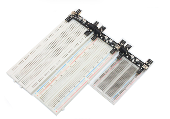
For example: Black Wings- 3.3v/5v Power Breadboard Adapter
This breadboard has two independent power supply design, one side of the switch is responsible for controlling the voltage, the voltage on both sides of independent design. Meanwhile groove design to maximize your bread board space savings.
About the Author


How to Send Micro:bit Data to ThingSpeak IoT Platform
January 11, 2018
VC0706 Camera Module DIY Guide
December 18, 2014

nRF24L01 Module Demo for Arduino
May 6, 2011


Children’s Programming Education is the Future Trend
March 20, 2024


ELECFREAKS AI Smart Lens Now Compatible with Gigo Building Blocks!
February 21, 2024


Comments