Master Your Micro:bit with Arduino IDE ——Light LED
If you had ever played micro:bit, you might be deeply impressed by makecode block method programming. It is easy and funny to operate or learn just like playing games. However, for some senior players, this funny programming method brings some troubles to them. As you dip further into the study, you will definitely observe the shortcomings of makecode. Since the code is sealed in bricks, we can not check the base code, therefore we can not operate the bottom hardware. It is not convenient for us to organize large code. Shortcomings are like that and so on. Most makers step into the area with Arduino as their beginning. No one can be more familar with Arduino than them. On one aspect, Arduino has abundant library files, which can greatly improve motherboard's extension ability; on the other aspect, there are a lot of ripe communities and thousands of study cases. It is completely the heaven of makers. Then, is it possible to play micro:bit well with Arduino IDE? The answer is definitely "Yes". This tutorial courses aim at teaching you to program for micro:bit with Arduino IDE.
Preparations:
You have to prepare a micro:bit board. If you do not have one at hand, you can buy from here:
Install serial port drive
How can we know whether we need to install a serial port drive program?

Open your computer's device manager, connect micro:bit to the computer with a USB cable and see if the port has a new serial device appeared. If it has, then you don't have to install a serial port drive program. If it hasn't, then you have to install a new one. Here's link for downloading serial port drive program: mbed_serial_port_device_for_win7. Before installation, please make sure that micro:bit is connected to computer with a USB cable. Note: If your computer system is win7, it usually means you have to install a new drive program.If your system is MAC, win10 or Linux, then you don't have to do it. Just skip this step.
Install Arduino IED
You can download Arduino IED here???/span> https://www.arduino.cc/en/Main/Software.
Add nRF51 series main board
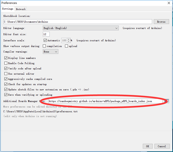
The core chip of micro:bit is nRF51. We have to add nRF51 series main board into Arduino IDE. Open Arduino IDE, click "File>Preferences" . Input “https://sandeepmistry.github.io/arduino-nRF5/package_nRF5_boards_index.json” into “Additional Boards Manager URLs”. If you have written URLs before, then you need to use a comma to split them.
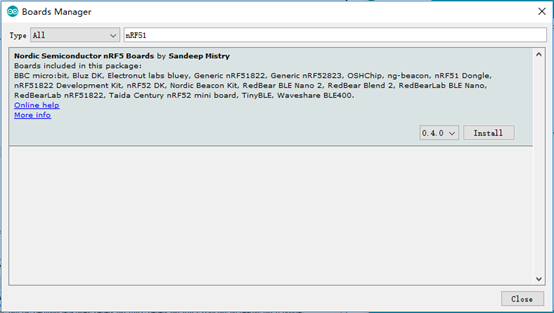
Click "Tools>Board> BoardManager", search the key word for nRF51 in the boards manager and download the development board.
Once it is done, click "Tools>Board" and choose micro:bit.
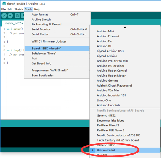
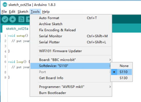
Set SoftDevice to be S110.
Choose micro:bit as the port after you have plugged your micro:bit into computer with a USB cable.
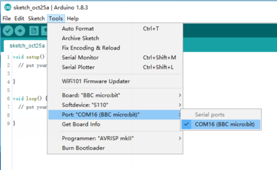
Everything is ok now. Till this step, we have completed all of Arduino IDE setting procedures.
Program Example
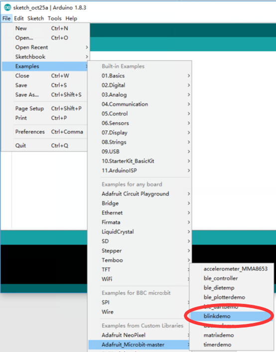
You can open an example and take a look. Click "File>Examples>Adafruit_Micro:bit-master>blinkdomo".
[cceN_cpp] const int COL1 = 3; // Column #1 control const int LED = 26; // 'row 1' ledvoid setup() { Serial.begin(9600); Serial.println("microbit is ready!"); // because the LEDs are multiplexed, we must ground the opposite side of the LED pinMode(COL1, OUTPUT); digitalWrite(COL1, LOW); pinMode(LED, OUTPUT); } void loop(){ Serial.println("blink!"); digitalWrite(LED, HIGH); delay(500); digitalWrite(LED, LOW); delay(500); } [/cceN_cpp]
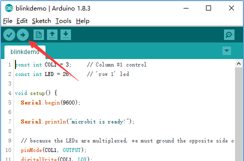
Click Upload to download the example code into micro:bit. Then you will see LED on the leftmost corner of micro:bit matrix is flashing. Open Serial Monitor in Arduino IDE.
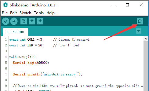
Set baud rate to be 9600.
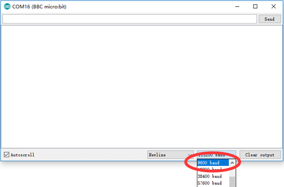
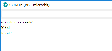
Then you will see the following display in Serial Monitor after you have set the baud rate.
How to light one LED bead on micro:bit randomly?
Actually, the LED matrix on Micro:bit is divided into 3 rows and 9 columns, among which the eighth and ninth conjunction point in the second row have not connected LED. So it has 25 LED beads in total. You can refer to the circuit diagram below:
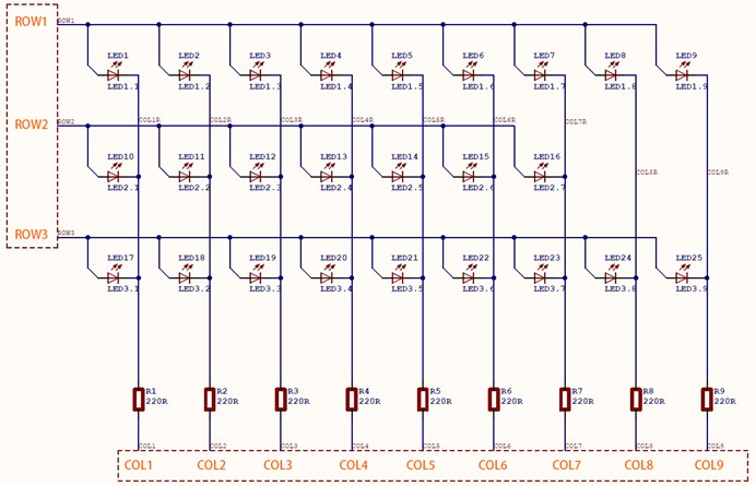
The row corresponds to high electrical level of IO while the column corresponds to low electrical level of IO. One thing we have to pay special attention to is not all of IO ports in rows and columns are leaded out by EDGE port. Here is the corresponding IDE PIN for IO ports in rows and columns:

You can see the corresponding rows and columns of every LED on micro:bit LED dot matrix.
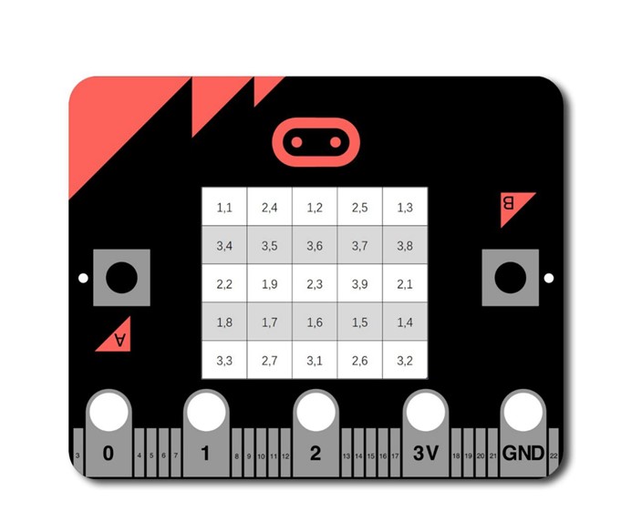
Let's me show you an example. Suppose if we have to light the very center LED bead on micro:bit LED dot matrix, we can check out its row and column axle to be (2, 3) from the above picture. Then we can find the corresponding IDE PIN of the both terminals of LED are 27 and 10.
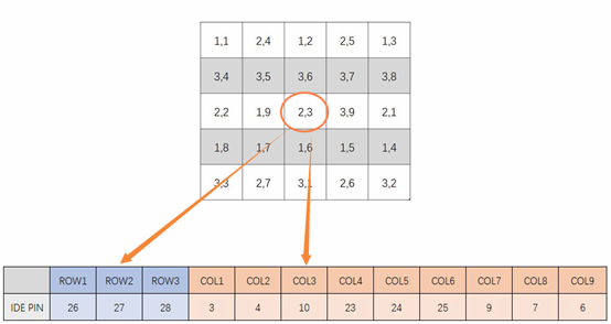
Set high electrical level to PIN 27 and low electrical level to PIN10, then we can illuminate the center LED bead. You can see the program below:
[cceN_cpp theme="dawn"] void setup() { // because the LEDs are multiplexed, we must ground the opposite side of the LED pinMode(10, OUTPUT); digitalWrite(10, LOW); pinMode(27, OUTPUT); digitalWrite(27, HIGH); } void loop(){ } [/cceN_cpp]
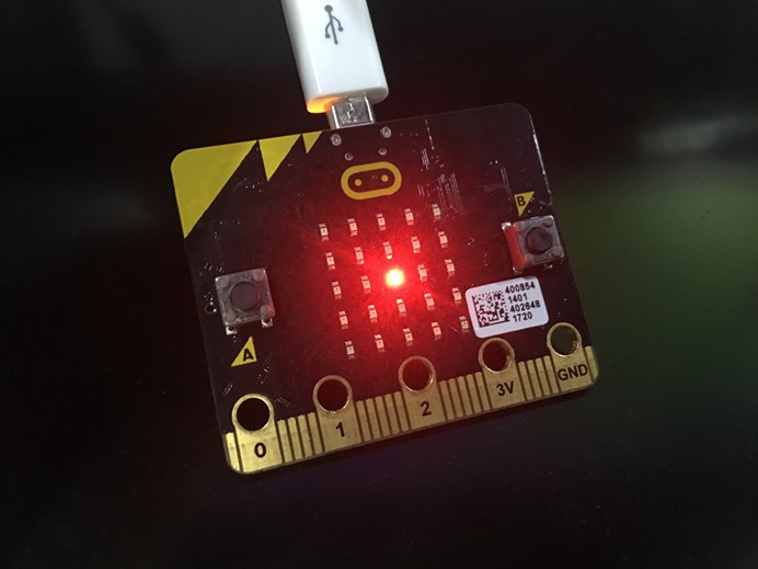
Upload this code to micro:bit, we can find the center LED bead on micro:bit LED dot matrix is illuminated.


Comments