

Unofficial Google Cardboard v2.0 Release
January 10, 2019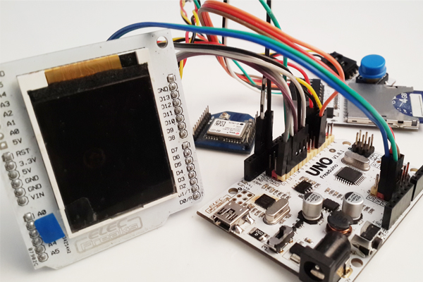
Arduino GPS Map Navigation System
January 10, 2019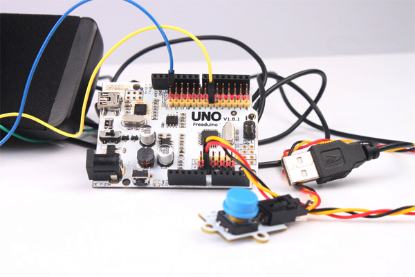
Talking about using Arduino to play music, is it the Arduino MP3 shield not the first thing you come up with? Or maybe some geeks will consider about tone() function? They are not the things our topic is about today. We don’t need any MP3 shield, tone(), or SD card. Only Arduino can perfectly play the music you like. It’s cool. Do-it-yourself a home-brew MP3 player for dear daddy or little daughter is fascinating. If you got a small Freaduino Nano or Freaduino Pro to put this into fact, then I’m sure ipod won’t be your consideration. But specifically how do you make it? Let us take a look. PS: For the demo we’re gonna show you, since the RAM for the Arduino is very small, hence we can only keep a 2-3 second music. Use a SD card, there’ll be no time limitation. See Arduino Simple Wav Player 2 using SD card.
I. Overview
Integrated with the homemade low-pass filter, this Arduino-based simple WAV player is to send out PWM signal generated by UNO, then through the low-pass filter and make the PCM data stored in the flash of UNO into sounds. Basically, the player cannot be regarded as a pure WAV playback, because by extracting the data from the WAV file and storing it in an array format in UNO, this tutorial is for reference. You can make SD card based WAV player by referring to this idea.
The WAV player is easy to make on different platforms and applicable for various scenarios like voice broadcast system, electronic keyboard, as long as you understand the principle of sound.
II. The Principle
2.1 Digital Audio
2.1.1 Digital Audio Basics
The basic principles and methods of digital audio processing technology is to use ADC, the analog digital converter, to take sample, quantize, encode and convert the analog audio signal into digital data and files to be saved. Of course, during the playback, the digital data goes through the DAC digital analog converter to restore the analogy signal form to be played out by the sound device.
Depending on the application range of the audio signal, the sampling frequency and the quantization accuracy of the analog audio digital 0ADC varies. The following table shows the common standard:
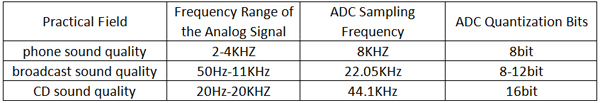
As you can see from the above table, according to the sampling theorem, for audio signal with different qualities, the digital audio ADC sampling frequency is twice the highest frequency analog signal. Additionally, the higher sound quality you require, the higher ADC quantization bits. In fact, the human ear cannot tell 1/256 level (8) precision changes, but for the CD sound quality, we use 16 quantization bits, precision 1/65536. Apparently, the better sound quality a digital audio has, the greater the amount of data it has to deal with. As for a second audio signal, when it’s a telephone-level quality digital audio, the amount of data is 8k bytes with each byte stored the level value of one sampling point. To obtain a CD-level quality digital audio, the data amount for every second is 88.2k; that amount is 176.4k for a two-channel stereo.
The most typical digital audio data file is WAV, which is mostly by using the original PCM encoding to store the raw data for each sampling point. Without any compression, now we got a sound card(either integrated or stand-alone) with build-in microphone port, under the support of WINDOWS platform, we can record, that is, turn the sound into digital audio and save it in the computer. And this file we saved, is WAV format file. Therefore, when we follow the sampling frequency speed to read the audio data one by one, the file is converted to analog signal by DAC, thus, the sound can be represented.
2.1.2 WAVE Format Introduction
WAVE format (extension: wav) is one of the basic audio formats used in multimedia digital audio, which is based on RIFF format as a standard. RIFF is short for Resource Interchange File Format. The first four bytes of each WAVE file is “RIFF”.
WAVE files are composed of several chunks (blocks). According to their positions in the file, they are: RIFF WAVE chunk, format chunk, fact chunk (optional), data chunk, LIST chunk (optional), etc. Of all listed above, except for RIFF WAVE chunk, format chunk, data chunk, the others are optional.
2.1.3 Get PCM Audio Data from WAV Files
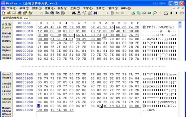
There are many WAV format files in PC. In fact, all prompt tone WINDOWS uses WAV format files. We can certainly create whatever audio file we need with the software on the PC. In the materials we provide a WAV file “talking microcontroller.wav” for readers. You can use the software WINHEX to view the specific content of the file in binary format (displayed as hexadecimal). The picture below tells how to display the content of the file by using INHEX.
According to the previous introduction of the WAV format audio file, you can find out the audio data part. The chunks have been marked in the following picture, and the parameters have been listed.
2.2 PWM
2.2.1 Introduction
PWM, is abbreviation form for “Pulse Width Modulation”. It is actually a very effective technology in the field of using microprocessor to control the analog circuitry, widely used in measurement, communication, power control and conversion and many other fields.
2.2.2 PWM Generation
The most common function of the microcontroller is timing. It’s a simple internal timer, when incrementing to a certain value, it returns to zero. PWM generates from these timers, outputs high level via the external pin. When the timer reaches zero and the output low level reaches another value, you can invert the two values. By this method, you can make the output pin remain at a high level within a particular time length, instead of switching its codes manually. If you output pin through a low-pass filter, you can get the average.
2.2.3 ADC Function Realization
The resistor R and the capacitor C on the PWM output pins simply constitute an integrator circuit. When filtering out high frequency to obtain smoothing, you can get the analog audio output at the audio output. Here, based on the example we provide, for a wav file, since the PWM frequency generated is 8 kHz, the PWM output signals contains many high-frequency signal components: greater than 8k. Therefore, the cutoff frequency of the low-pass filter composed of the resistor R and the capacitor C should be around 6 kHz so as to filter out signals with high frequency of over 8k, only to retain the analog signals with frequency under 4 kHz.
The cutoff frequency of the low-pass filter composed of the resistor and the capacitor is calculated by the formula: F=1/2∏RC. Introducing the numbers, here’s what we get: 1/(2*3.1415*2700*0.00000001)=5897.6Hz. Thus, when R=2.7k, C=0.01uF, the cutoff frequency of the filter is approximately 5.9 kHz.
III.Prepare
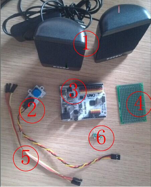
The hardware:
- USB mini speaker
- Digital push button
- Freaduino UNO
- 4×6 cm universal board
- Dupont line
- Audio port
The software:
- AVR studio 4.19
- Winavr-2010
Note: Here I provide AVR studio routines since I think it more convenient to write some codes in AVR studio than Arduino IDE. You just need to make a slight modification before you can use the codes in the Arduino IDE.
IV. Make
- Solder the low-pass filter on the 4×6 com universal board by referring to the following circuit diagram.
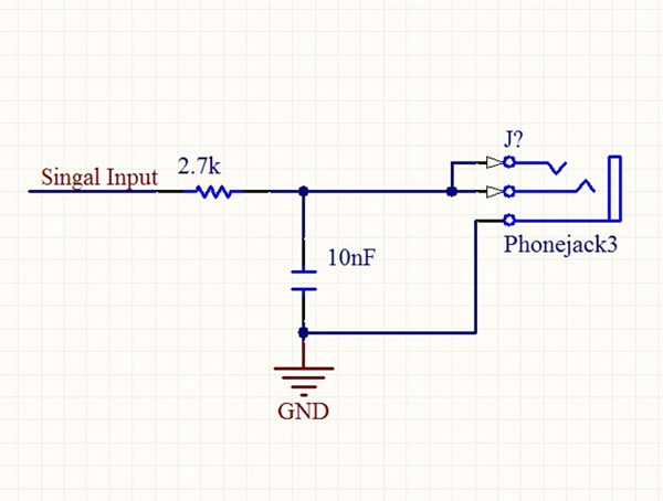
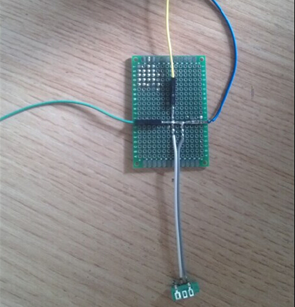
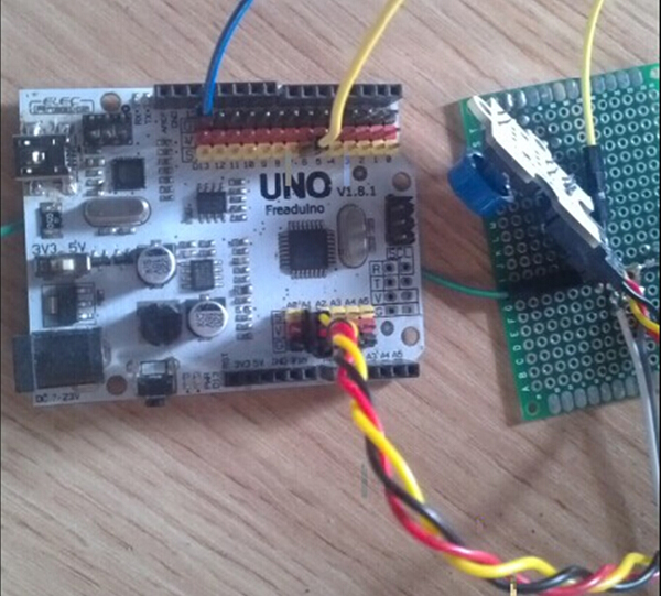
2. Connect the “Signal Input” on the low-pass filter with D6 on UNO; wire the filter and UNO to the common ground.
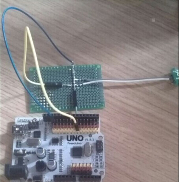
3. Plug the digital button into A1 on UNO. As shown below:
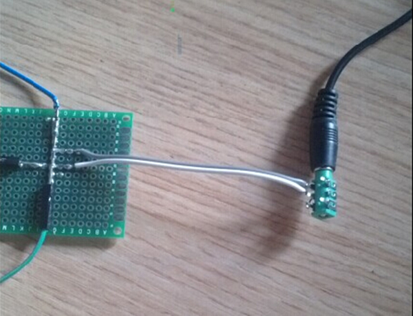
4. Plug the audio jack of the USB mini speaker into the audio port of the output end of the filter.
After the above steps are completed, power up the UNO and download the codes into it, press the digital button and then you will hear the sound from the USB speaker.
Download the codes here.