Pico:ed is powered by the latest MCU release from the Raspberry Pi Foundation (RP2040), the first microcontroller for the Raspberry Pi. It brings our signature value of high performance, low cost, and ease of use to the microcontroller space.

With a large on-chip memory, symmetric dual-core processor complex, deterministic bus fabric, and rich peripheral set augmented with our unique Programmable I/O (PIO) subsystem, it provides professional users with unrivaled power and flexibility. With detailed documentation, a polished MicroPython port, and a UF2 bootloader in ROM, it has the lowest possible barrier to entry for beginner and hobbyist users.
RP2040 is a stateless device, with support for cached execute-in-place from external QSPI memory. This design decision allows you to choose the appropriate density of non-volatile storage for your application, and to benefit from the low pricing of commodity Flash parts.
RP2040 is manufactured on a modern 40nm process node, delivering high performance, low dynamic power consumption, and low leakage, with a variety of low-power modes to support extended-duration operation on battery power.
Key features:
30 GPIO pins, 4 of which can be used as analogue inputs
Adopting a more rounded shape: the head is changed to a curved shape and the pin edge is wavy, which makes it less likely for users to hurt their hands when using it.
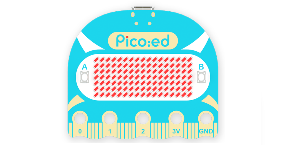
There is a start-up selection button, reset button, onboard 2MB Flash chip, RP2040, 12M crystal, etc.

1.3.2.1 Start selection button
Normal boot via Flash, then BOOTSEL button, connect the USB cable to the PC, then release the BOOT SET button, it will enter the UF2 download mode.
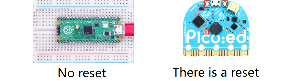
1.3.2.2 Reset button
There is no reset button on the official development board, so you need to plug and unplug the USB cable every time you download new firmware.
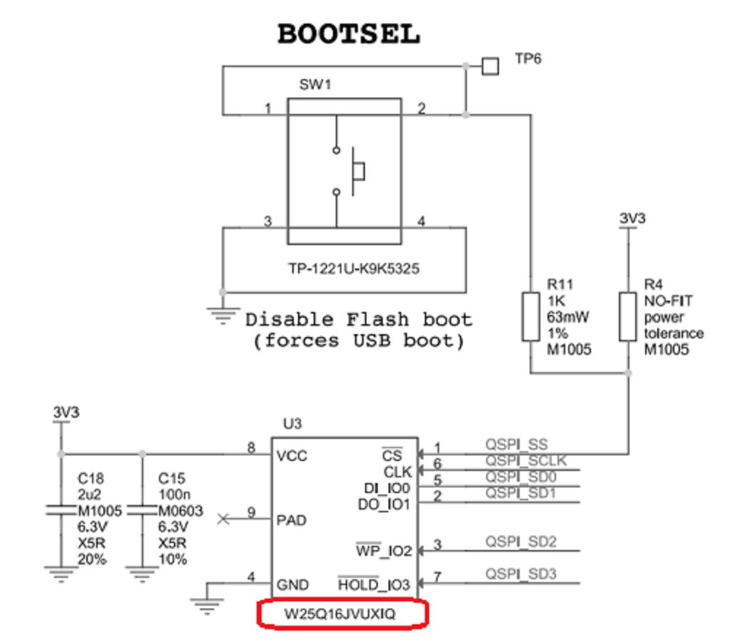
1.3.2.3 Introduction of flash
It is mainly used to store code data and communicate with MCU through QSPI bus.
The Flash used in Pico:ed is W25Q16 from Huabang Electronics, which has 2MB of on-chip space, but the RP2040 supports up to 16MB, so it can be replaced with a larger flash.
1.3.2.4 Introduction to crystals (with and without crystal description)
Pico:ed uses a 12M crystal, with the option of using an on-chip RC oscillator. However, Pico:ed can achieve strict timing requirements with the use of 12M crystal.
If you have used the products of the EF series, you will know how rich the ecosystem is, backed by such a powerful ecosystem, there is a large part of the attention of the ecological and creator players, who need to be even said to be fans.


Why is the chip called RP2040?
The post-fix numeral on RP2040 comes from the following,

Number of processor cores (2)
Loosely which type of processor (M0+)
floor(log2(ram / 16k))
floor(log2(nonvolatile / 16k)) or 0 if no onboard nonvolatile storage
We can also feel that Raspberry Pi official has a clear plan for the product and also shows that in the near future Raspberry Pi official will launch more MCUs to build a better ecosystem.
Is the description of the development environment content micropython, c and c++.
Additional support for the operating system RT-Thread integrated compilation environment ide of Arduino is also supported.

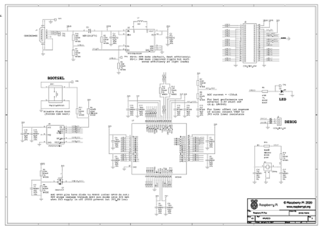
The analysis of the Pico:ed schematic will be divided into the power supply circuit, power supply circuit, chip peripheral circuit, circuit of Boost button and Flash, clock circuit, ADC sampling circuit, and LED circuit.
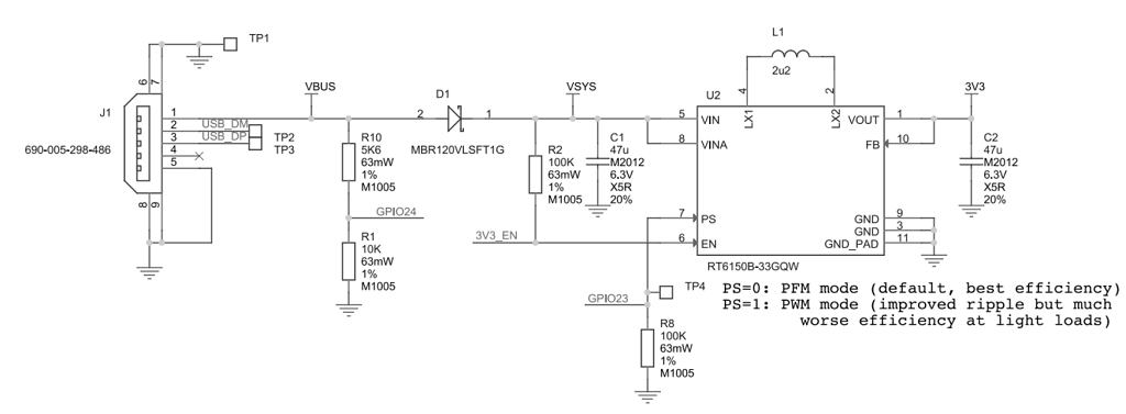
Under normal circumstances, the micro USB port is connected to the PC or Pico:ed’s USB port via a micro USB cable.
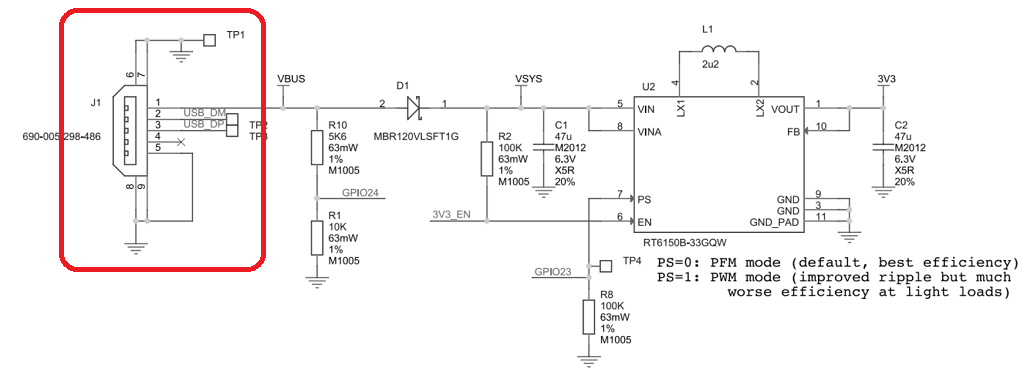
That is to say, VBUS is normally a 5V 500mA power input.
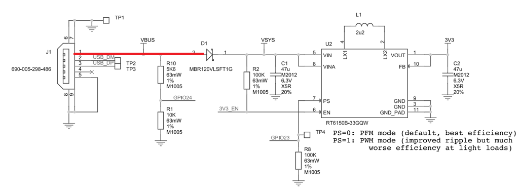
There will be a voltage drop of 0.1V to 0.2V through the D1 Schottky diode.
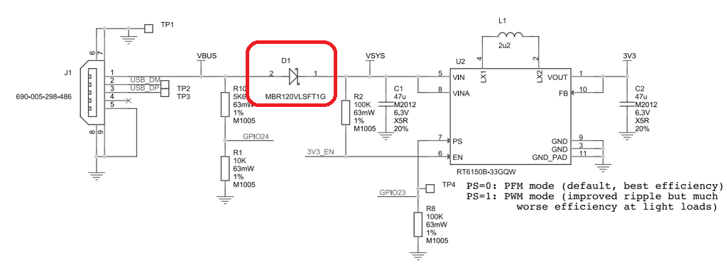
The voltage at VSYS is about 4.8V.
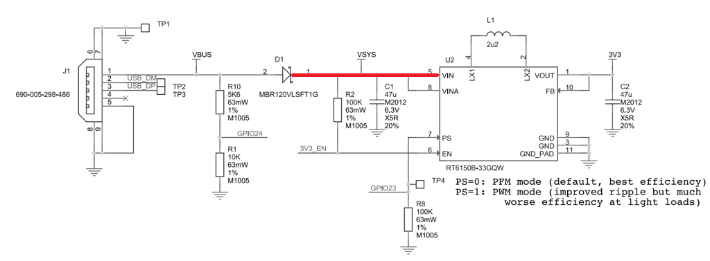
VSYS will pass through a C1 ceramic capacitor.
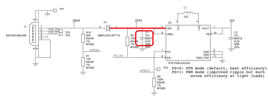
Input to RT6150B-33, which is a DC-DC boost converter chip.
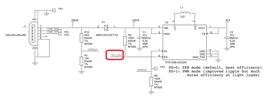
Its input range is 1.8V~5.5V and output is 3.3V, where the pin 3.3V_EN is the enable pin.
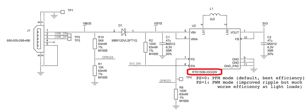
The normal condition is a weak pull-up to VSYS via R2.
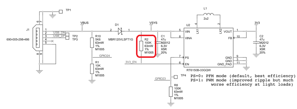
The DC-DC chip works at this time, but it can be turned off at 3.3V by using the 3.3V_EN pin.
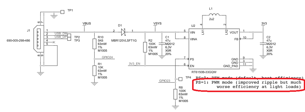
In addition, the PS pin position is grounded by default and is weakly pulled down to the ground via R8.
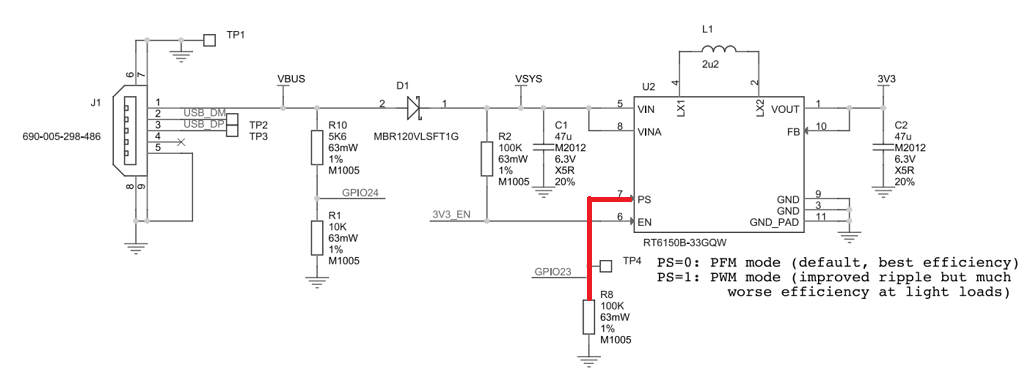
At this time the DC-DC chip works in PFM mode which has a high conversion efficiency.
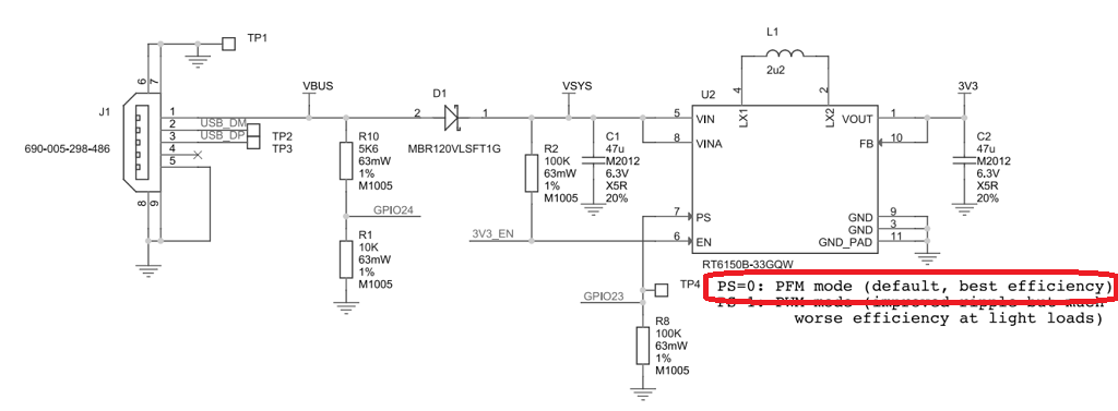
It can also be operated in a PWM mode by applying a pull-up on GPI0 pin 23.
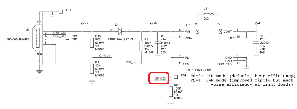
This mode causes it to be less efficient, but the ripple will be smaller.
Officially, three types of power supply are provided to safely power Pico:ed in a way that can be chosen independently.

The Raspberry Pi Pico can be powered via the device’s own Micro USB connector, just like in figure (a).

It is also possible to carry out a power supply input through the VBUS pin that is 5V.

Power can also be supplied using the VSYS pin, which can be fed from 1.8V to 5.5V.

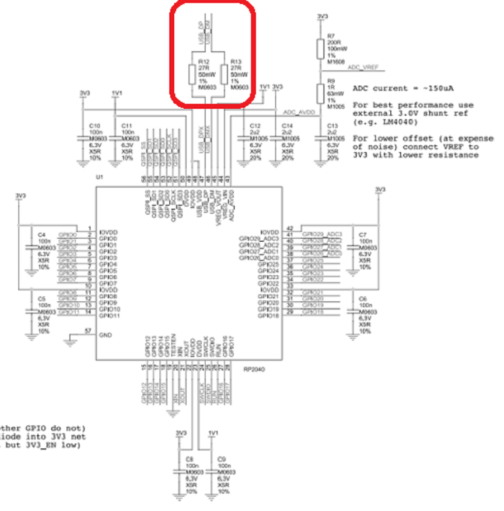
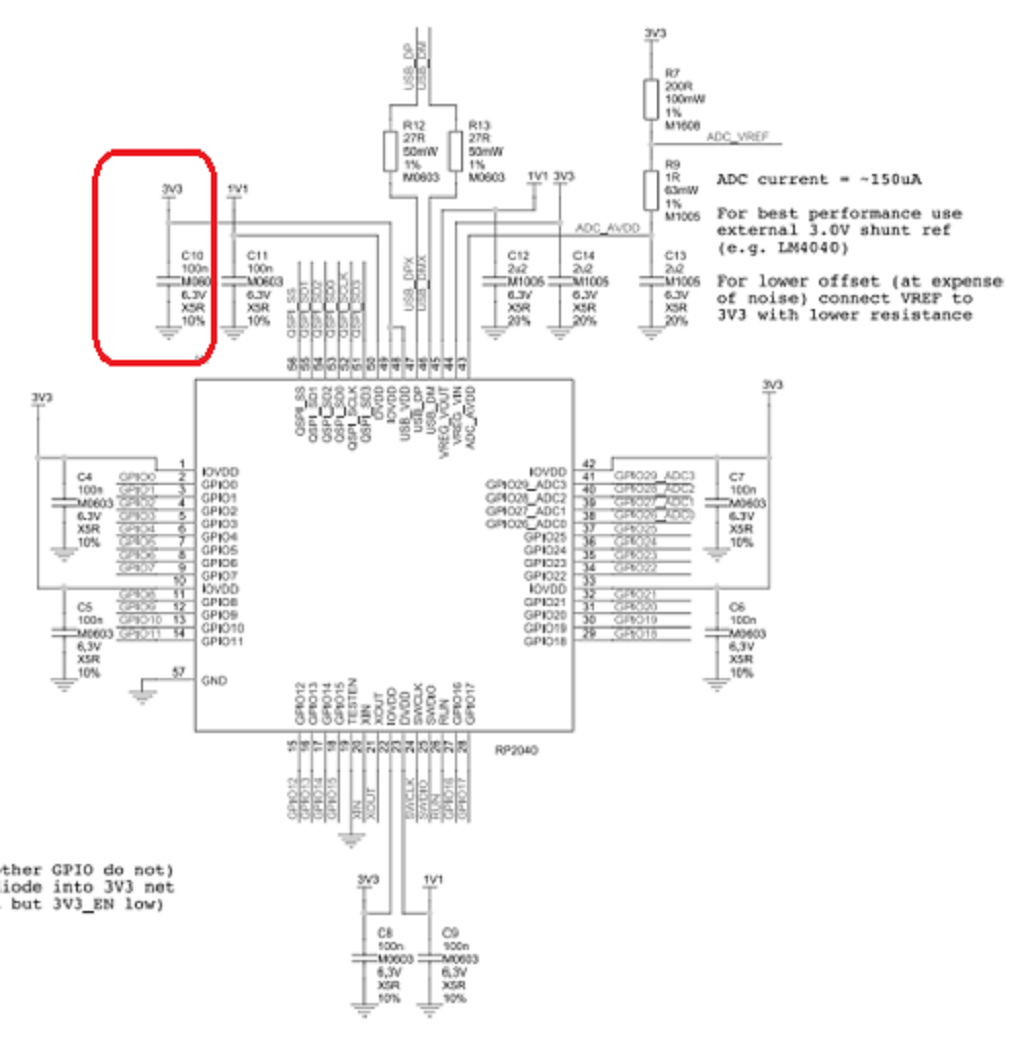
The following diagram shows the peripheral circuit of the chip RP2040 and will explain several key points.
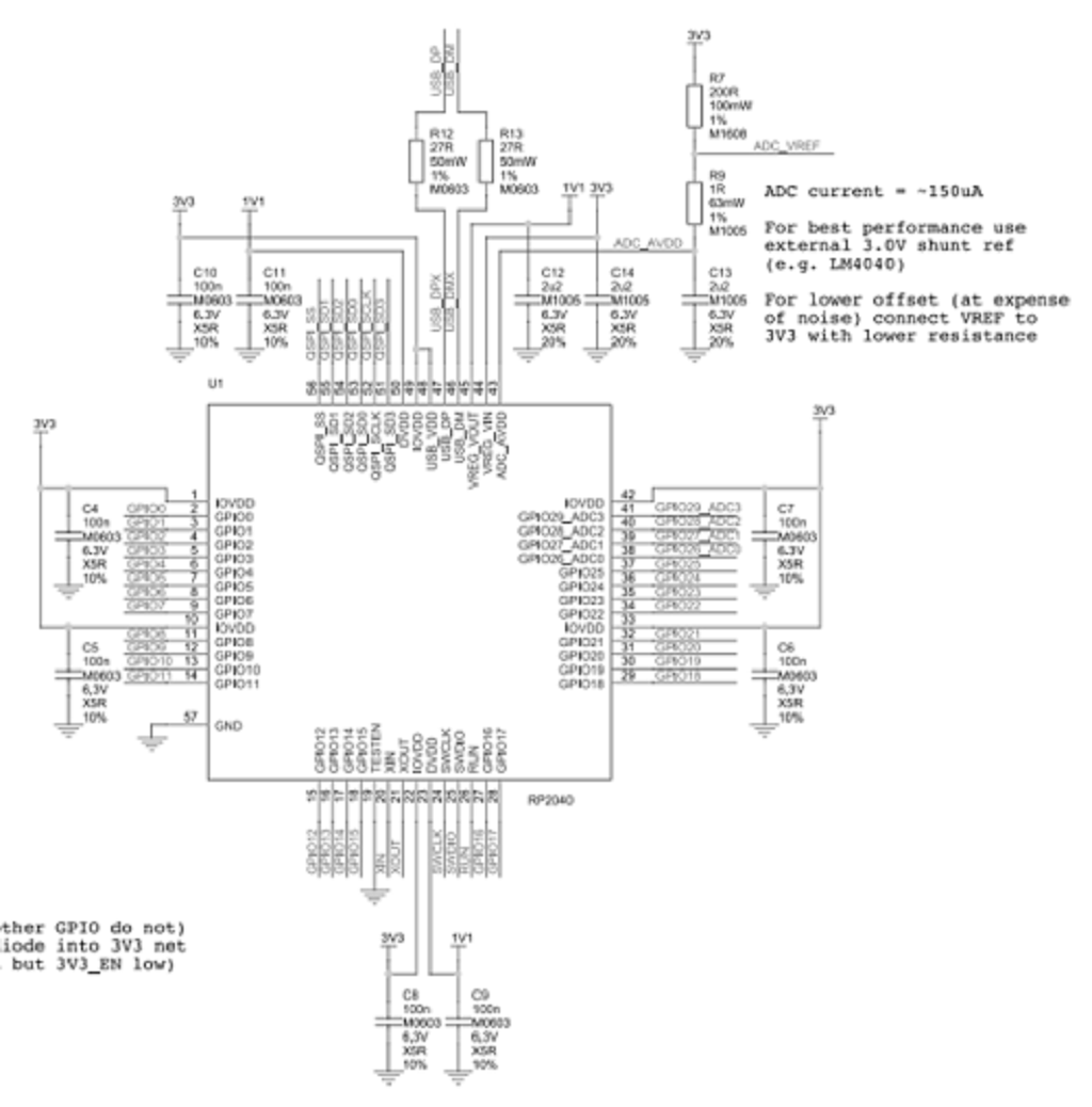
The USB pin coming out of the chip must be connected in series with two 27-ohm resistors to the outside, not directly.
The ADC reference voltage is provided by default with 3.3v on the board, but it can also be debugged with an external 3V reference power supply.
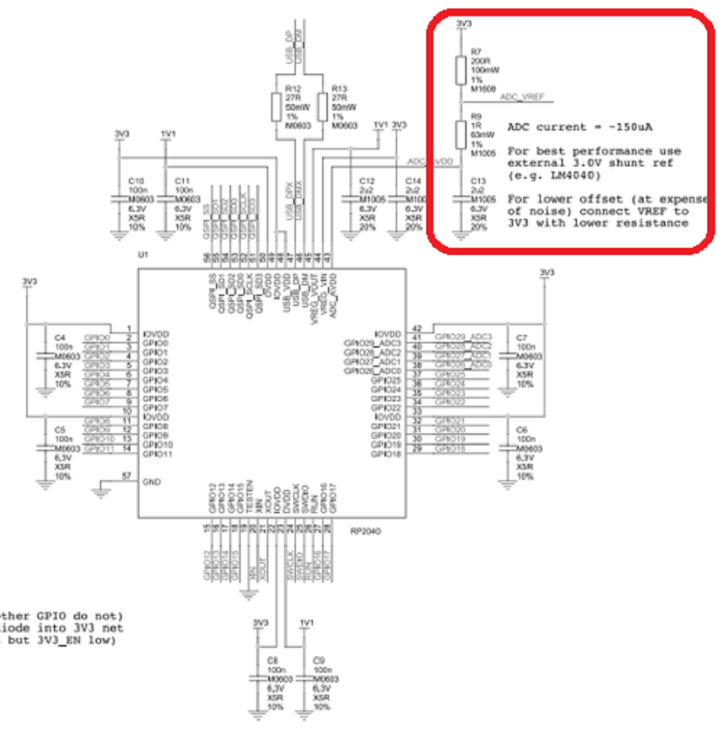
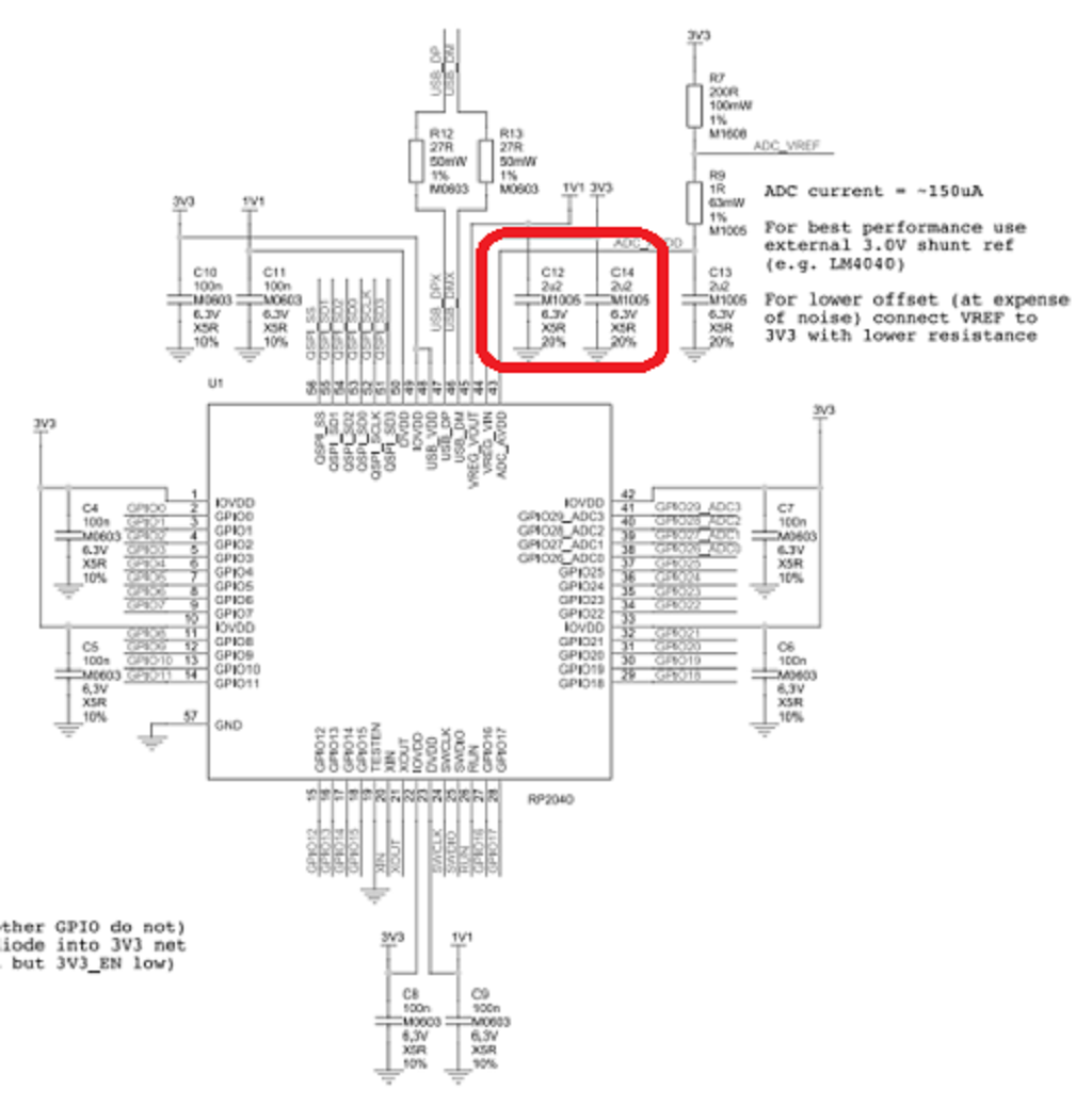
Here is the input of the internal core power supply regulator, it is necessary to appropriately increase its capacity, here is the use of 2.2uF filter capacitors.
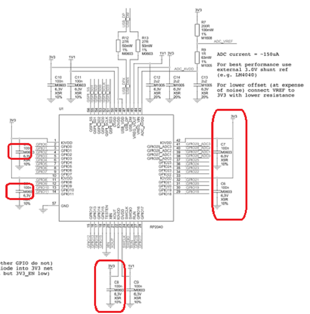
IOVDD is a GPI that uses a 100nF capacitor for filtering.
DVDD is the internal core power supply, using a 1.1V power supply, and can also use an external power supply for power supply.
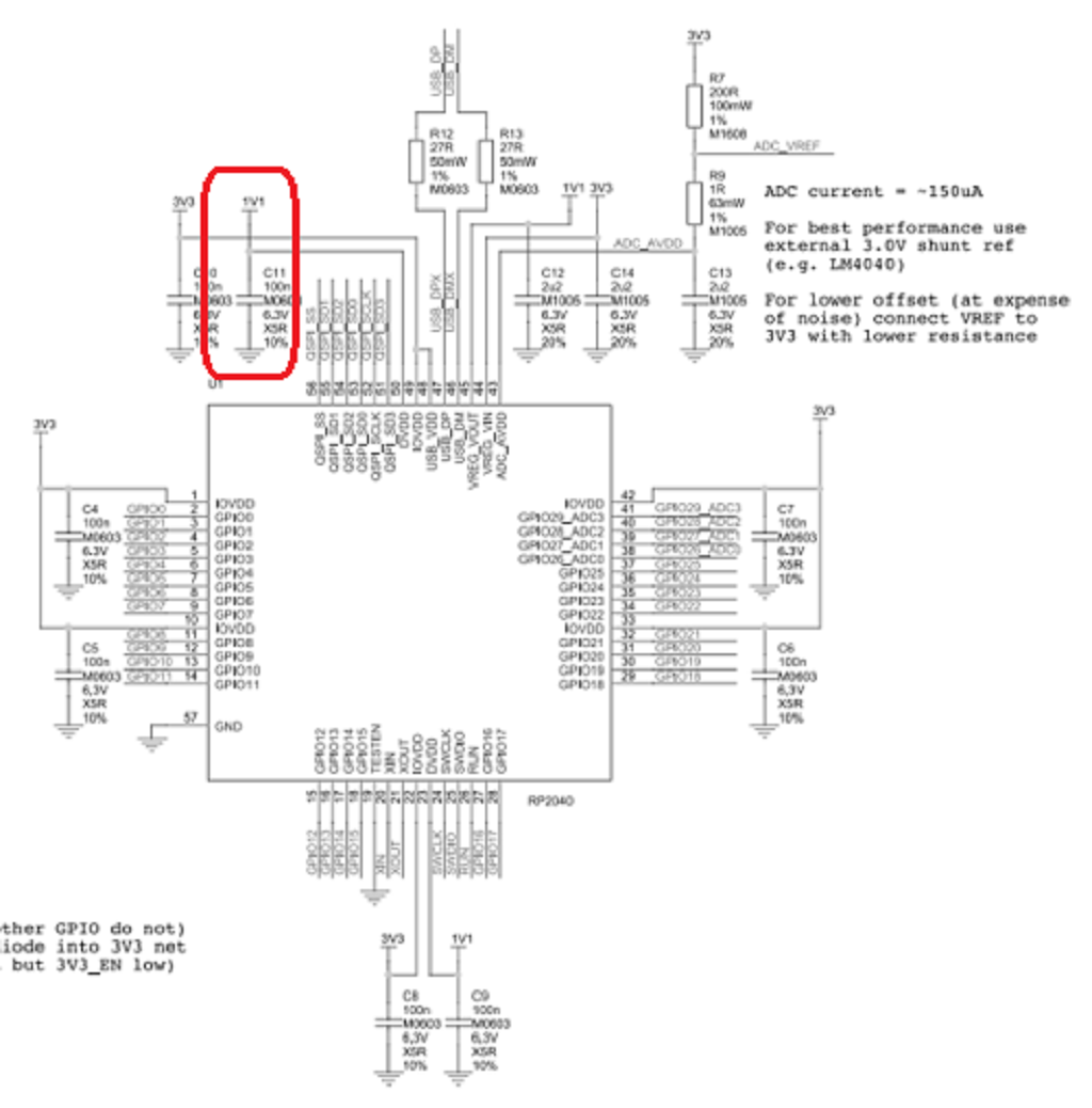
USB_VDD is the power supply for the USB full-speed interface, which uses a 3.3V supply.
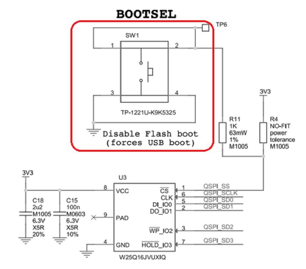
See the Boost button and the Flash circuit.
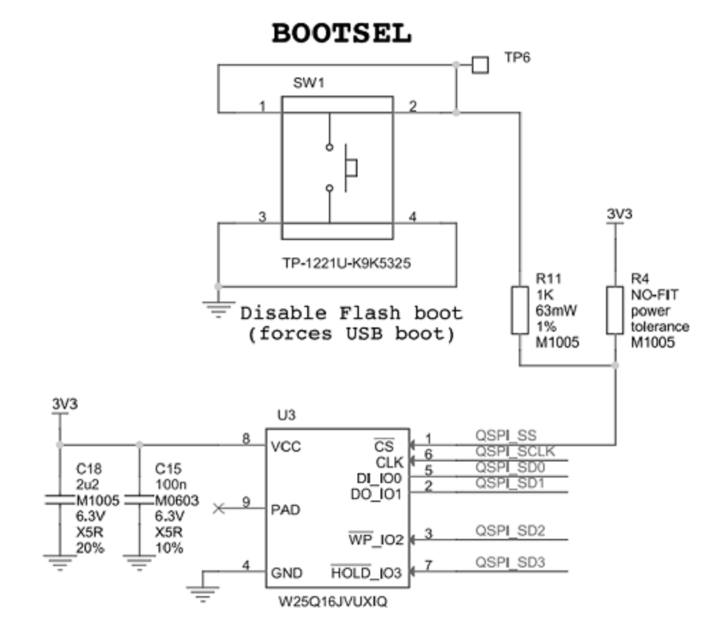
The BOOTSEL button is not a reset button but a boot select button.
When the button is not pressed, MCU reset or power up will boot from Flash.
When the button is pressed and the MCU is reset or powered up, it will enter UF2 download mode.
The Flash used is the W25Q16 from Warbon Electronics.
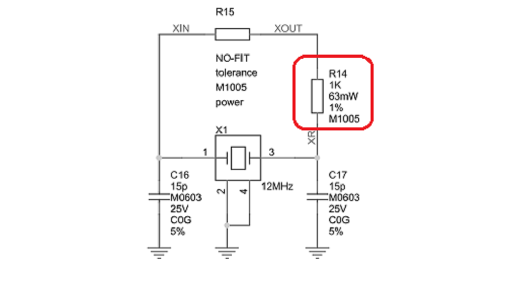
Now see the clock circuit.
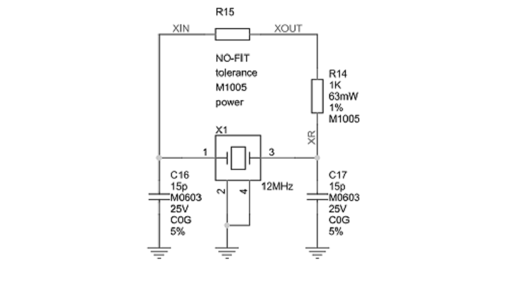
One point to note is R14, which is used to limit the current to prevent overcurrent from reducing the life of the crystal or damaging it.
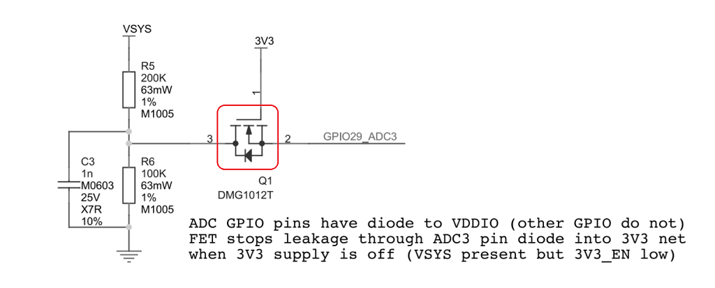
Now see the ADC sampling circuit.
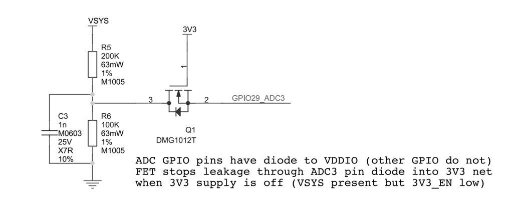
After R5 and R6 voltage division to get 1/3 of VSYS.
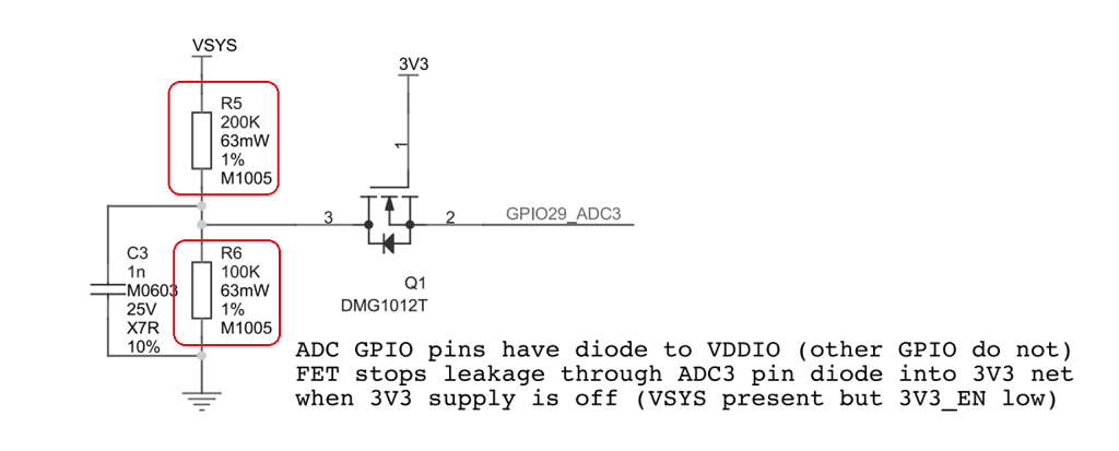
The N-MOS tube is used to prevent the VSYS current from leaking into the 3.3V network when the VSYS voltage of 3.3V is cut off.
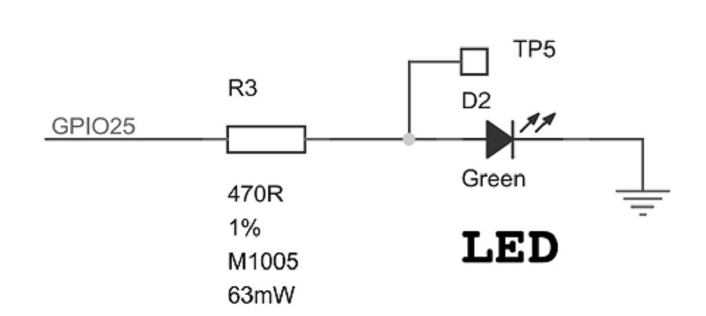
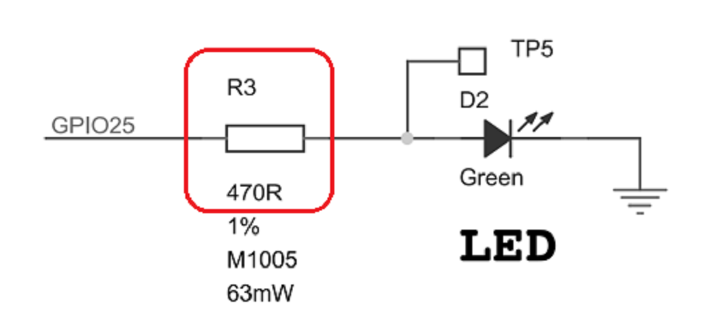
Here is the LED circuit.
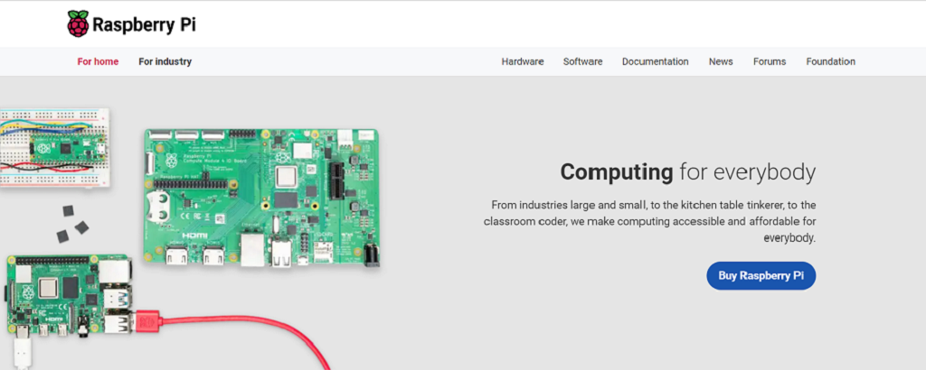
Go to the web https://www.raspberrypi.com/ , and download firmware for Pico:ed.
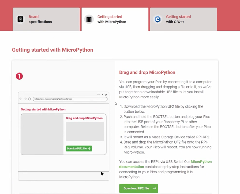
Once the download is complete, press the firmware download button on the back of the Pico:ed.
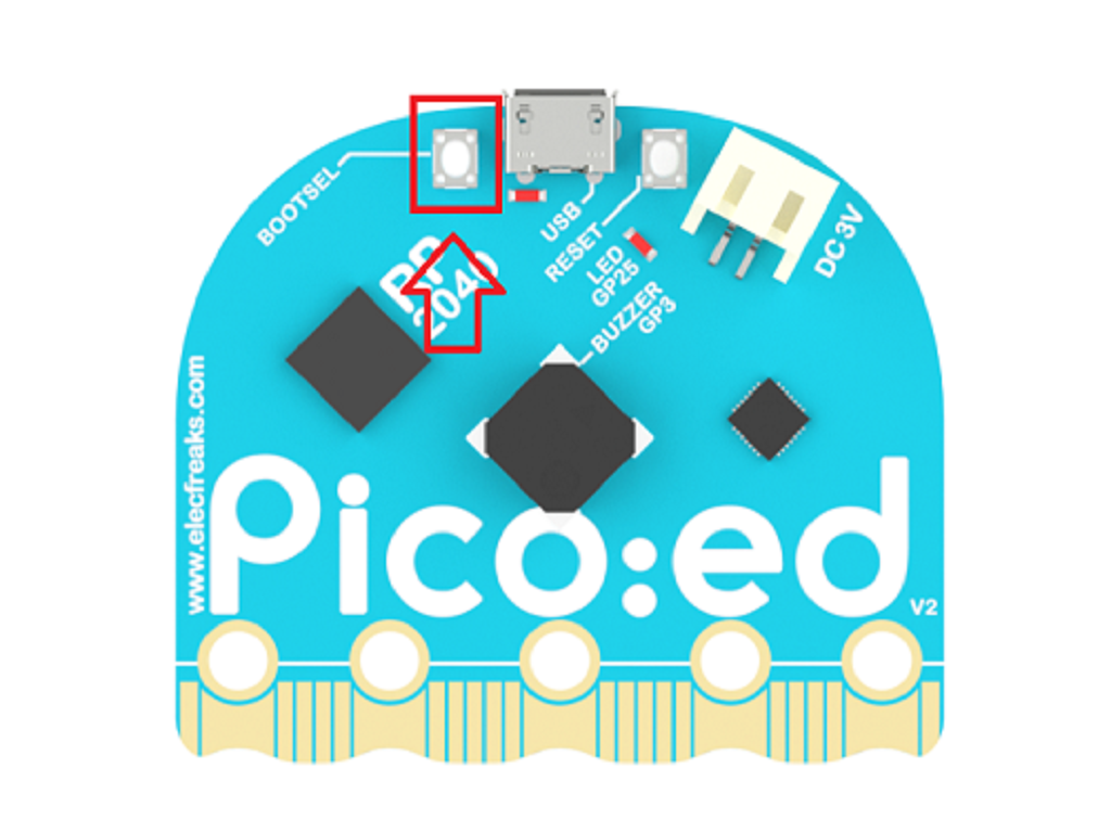
With the firmware download button pressed, plug in the USB cable and release the firmware download button when a disk symbol with the name RPI-RP2 appears on the computer side.

Send the downloaded firmware to the disk drive with the open name RPI-RP2.
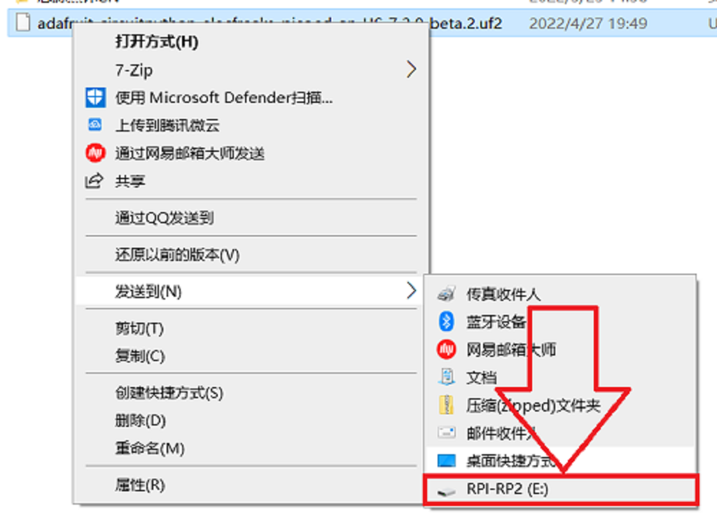
When the firmware is downloaded successfully pico:ed will automatically reconnect and the connection will be completed for a disk with the name CIRCUITPY.

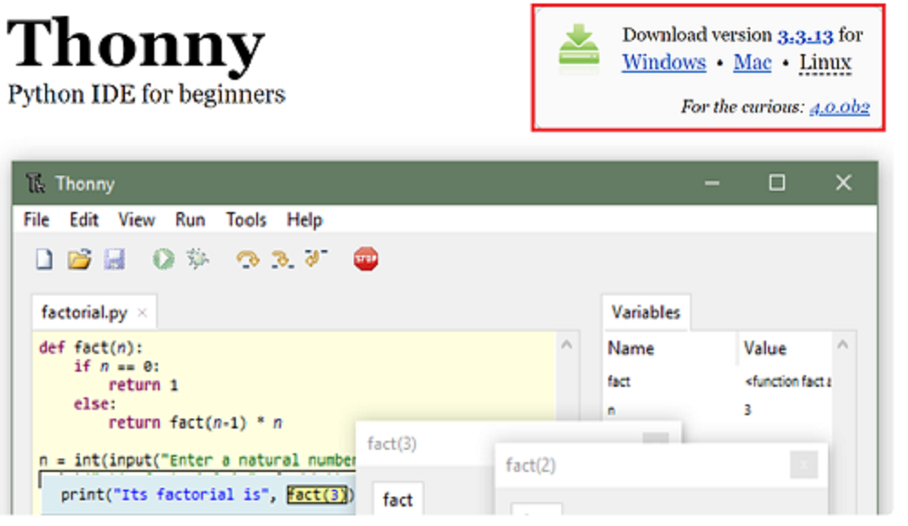
When you start writing Pico:ed code, we recommend using the integrated development environment Thonny, which you can install by choosing the appropriate version for your computer system.
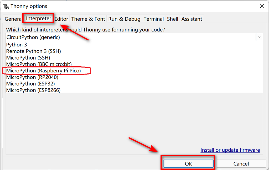
After the installation is complete open Thonny, select Tools in the menu bar and choose Options.
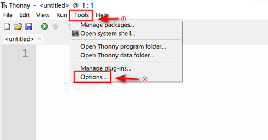
Select Interpreter in the menu bar of the pop-up window, click the drop-down arrow, select MicroPython (Raspberry Pi Pico), and click OK.
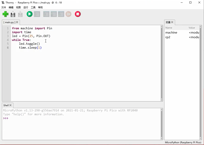
This program will make the LEDs flip every second, click Run, and Pico:ed will run.