Based on the hardware in the previous section, some of you will ask exactly how the LED lighting is achieved.
The answer is to use a GPIO peripheral.
Here you need to understand a concept, the full name of peripherals is external devices.
In the early days, UART, LCD controller, and so on, and the CPU is not on a chip, so that is called external devices.
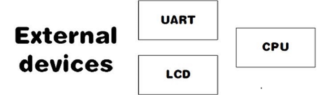
It has evolved with the semiconductor process and various peripherals have been integrated on a single chip, but are still referred to as peripherals.

We refer to peripherals external to the chip as off-chip peripherals.

Similarly, peripherals inside the chip but outside the core are called on-chip peripherals and are now simply referred to as peripherals.

Our first peripheral is the GPIO, known as General-purpose input/output.
Simply put the MCU, the pins that the MCU can directly control.

Now we need to really understand our first peripheral, the GPIO.
The full name is General-purpose input/output.
Simply, the MCU.

Pins that can be directly controlled by the MCU.

MCU is often connected to external devices via GPIO pins for control, reading, or communication.

GPIO is arguably the most important function of most MCUs and the main way to connect to the outside.
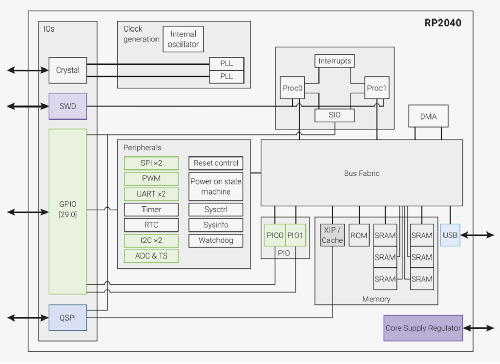
We can now see the system overview diagram for the RP2040 and it is easy to see that the kernel can control the GPIOs directly, via SI0(Software control of GPIO).
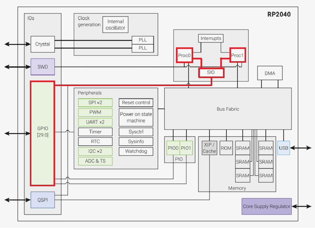
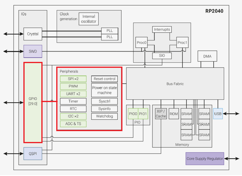
However, peripherals such as the SPI require a GPIO in order to implement the corresponding function.
Our light-up program is to light up or turn off the light-emitting diodes by controlling the GPIO output high or low.
We now understand how the GPIO implements the input and output functions.
We can now see that the output section is controlled by four parts.
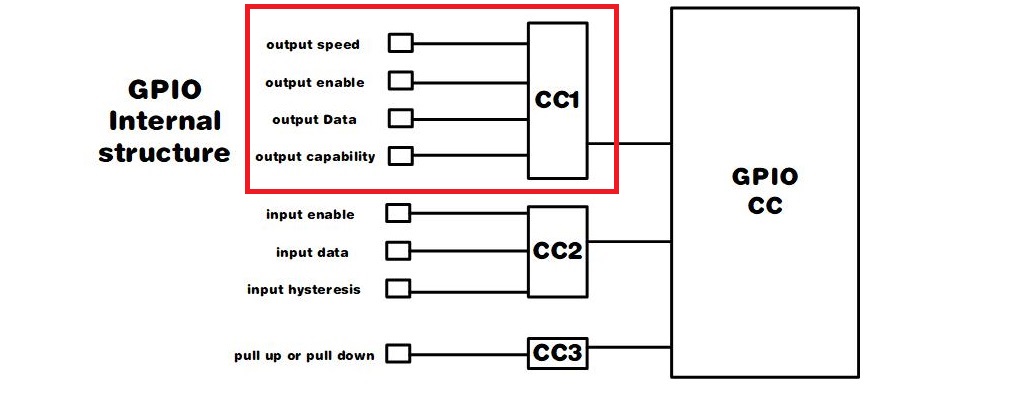
The output speed determines the fastest GPIO reversal speed.
Output enable determines whether the output is output.
Output data determines the output level.
Output capability determines the driving capability of the GPIO The input section then consists of three parts.
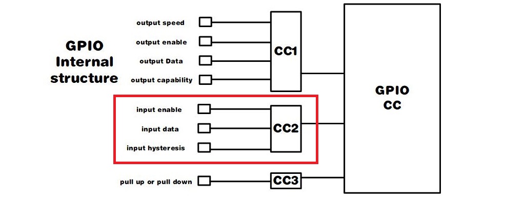
The input enable determines whether an input is possible.
Input data is the input GPIO level.
Input Hysteresis is whether or not a Schmitt trigger is used.
One thing to note here.
At this stage, MircoPython does not have control over the output speed, output capability, and input hysteresis options.
Based on the above structure the states of the GPIO can be divided into 4 categories: open-drain output, pull-up input, suspended input, and pull-down input.
Pin object constructor
id: GPIO number, the value is 0-29, if you use GPIO13 then fill in 13 here.
mode: mode, optional None, Pin.
pull: uses internal pull-up and pull-down resistors, valid only in input mode.
PULL_UP(1), Pin.PULL_DOWN(2).
value: Port value in output or open-drain mode, 0 is low (off), 1 is high (on).
Reinitialize the GPIO port.
mode: mode, selectable from None, Pin.IN(0), Pin.OUT(1), Pin.OPEN_DRAIN(2).
pull: Use internal pull-up and pull-down resistors, valid only in input mode.
None(0), Pin.PULL_UP(1), Pin.PULL_DOWN(2) are available.
Used to set external interrupts.
handler: callback function for interrupt triggering.
trigger: trigger condition, set to edge trigger or level trigger.
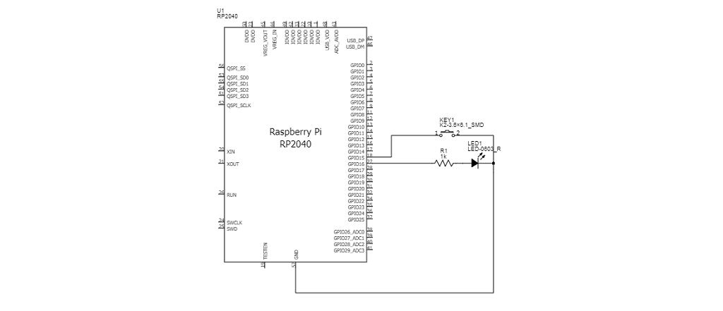
Here the key is connected to the GPI015 the external LED is connected to the GPIO16 and the current is limited by a 1K resistor. Control by writing a program.
Python
from machine import Pin
import utime
#Initialize GPI015,and set the pull-up input mode
button_num = 15
button = Pin(button_num,Pin. IN,Pin.PULL_UP)
#Initialize GP1016,and set the output mode
external_led_num =16
external_led = Pin(external_led_num,Pin.oUT)
#Initialize GPIO25, and set the output mode
led_num = 25
led = Pin( led_num,Pin.oUT)

print( "button gpio={0}".format( button_num))

while True:
    #led turn off
    led .off()
    #Read button value
    if( button.value()==0):
        utime.sleep(e.e1)
        if(button.value()==) :
        #Toggle led
        external_led.toggle()
        #led turn on
        led.on()

        print( "button is pressed")
        while(button.value()==0):
                utime.sleep(0.01)
]