
Pulse-Width Modulation, or PWM for short, is a scheme that uses digital signals to simulate changes in analog signals, as most of the signals in our natural life are analog, such as brightness, speed, volume, etc.

However, analog circuits tend to be more complex and less immune to interference so pulse width modulation was developed to approximate the analog output by outputting pulses of different widths at a fixed frequency to obtain a smoothly varying average voltage.
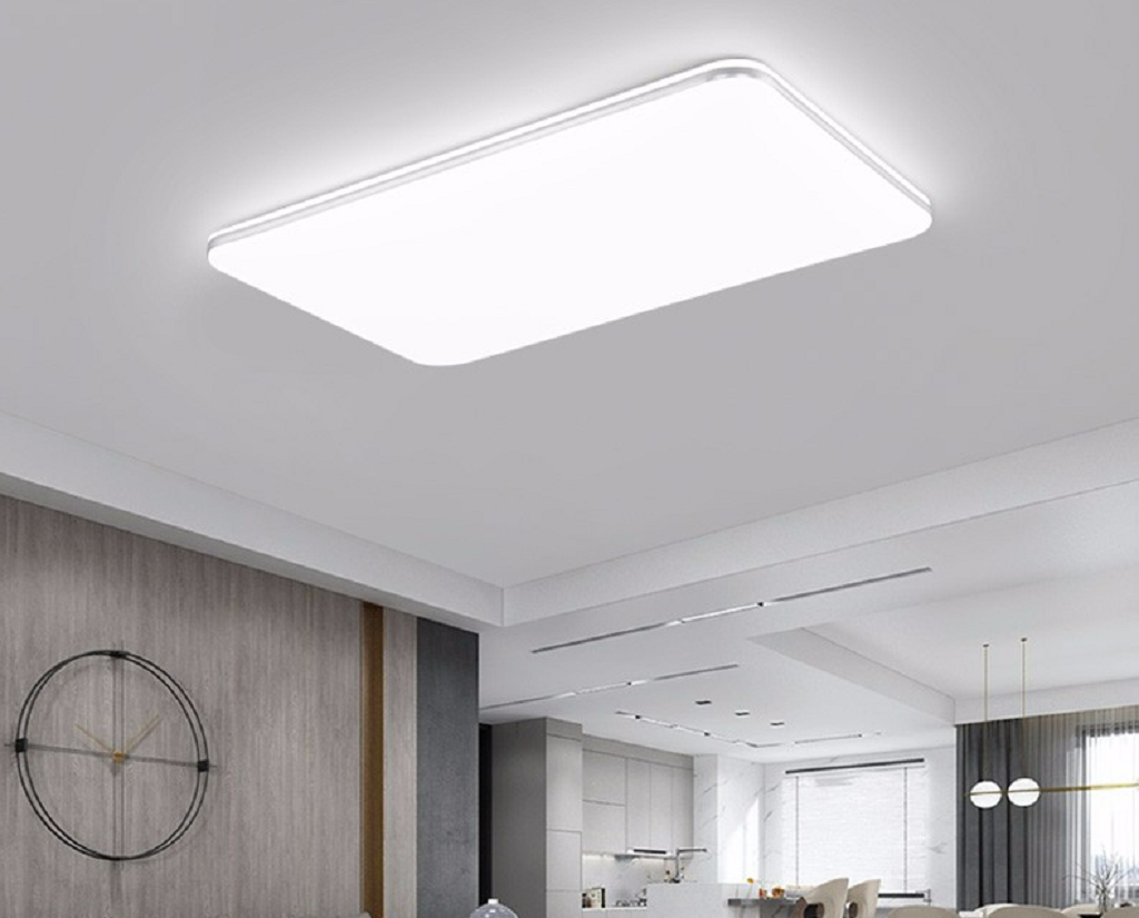
As digital circuits take up more and more of a place in our lives, PWM is becoming more and more common, for example, energy-saving lamps are now basically LED lamps. We can control the brightness of the light through PWM.
PWM technology may also be used in our most common mobile phone chargers. Having understood what PWM is and how it is used. Next, we will look at how the RP2040 implements PWM output.
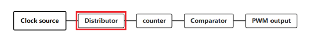
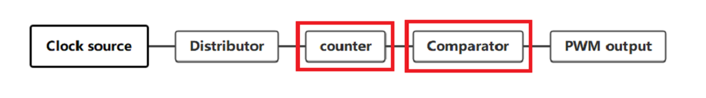
First, let’s look at the flow chart of the PWM.
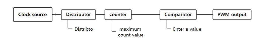
The clock source outputs the clock signal to the frequency divider.
The crossover is performed according to the crossover parameters.
The signal obtained by dividing the frequency is used as the clock source for the counter, which then counts.
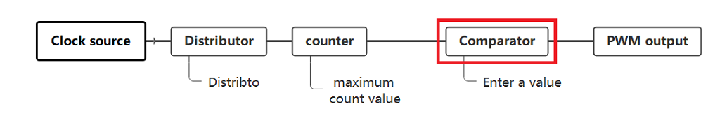
The comparator then compares the input values and outputs the corresponding levels.
Here is an explanation of the crossover and counter, which as the name suggests are used to crossover or downconvert the input signal.
If the input frequency is 100hz and the crossover parameter is 10, then the output signal of the crossover is 10hz.
Counter: This is used to record the number of pulses of the input signal.
Each time a clock signal arrives, the count value is increased or decreased by one, subject to the maximum count value.
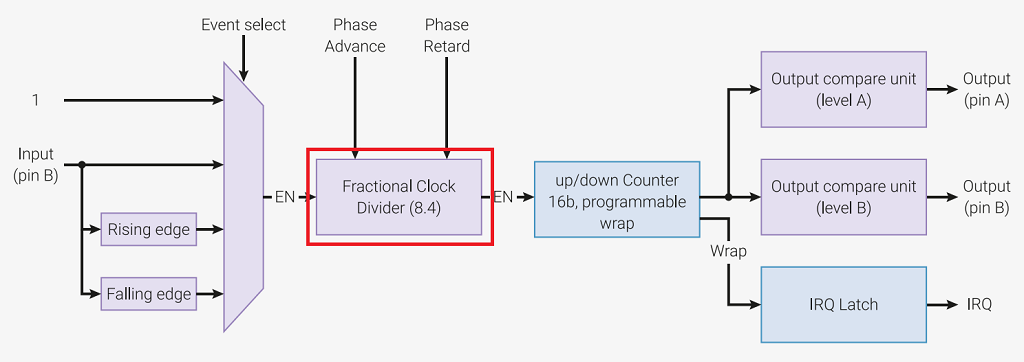
After a general overview of the PWM flow chart, we now see the internal PWM framework.
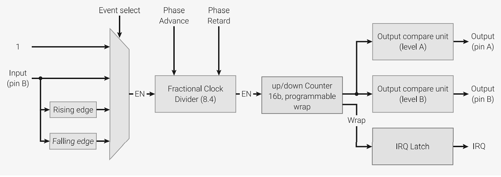
I will then break it down.
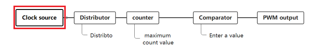
The first stage of the PWM peripheral is the selection of the clock source.
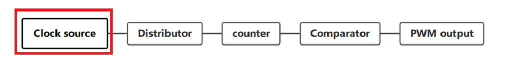
By default, the PWM channels run in free-running mode.
In this case, the clock source is the system clock.
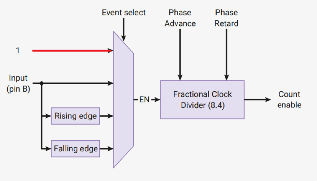
In addition to this, there are three modes:
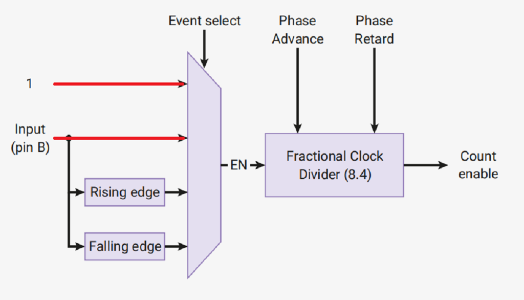
1. When a high level is detected on pin B, the system clock is used as the clock source, and when low, there is no clock source.
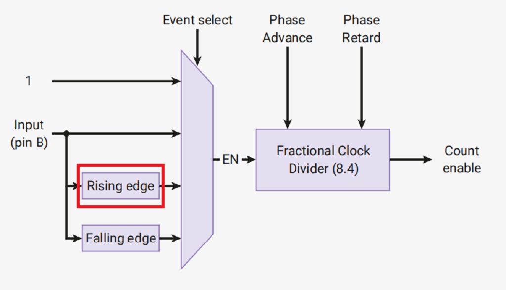
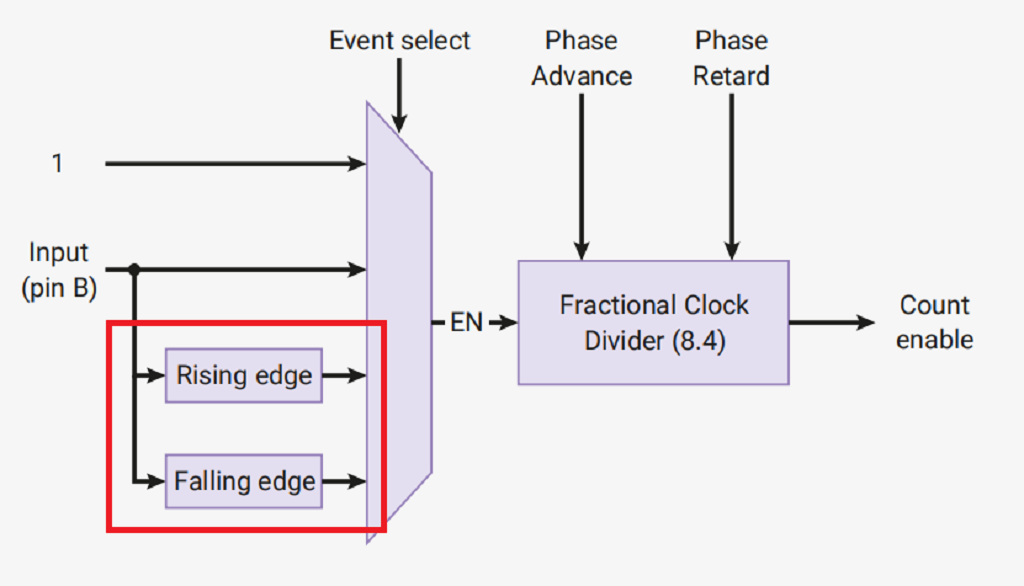
2. When a low to the high rising edge is detected on pin B, a pulse is sent out, using this pulse as the clock source.
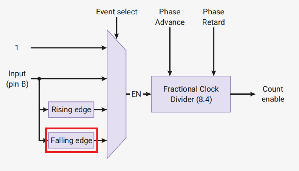
3. If a falling edge is detected on pin B when a high level is turned to a low level, a pulse is sent out and this pulse is used as the clock source.
Where we can refer to mode 1 as the level-triggered mode.
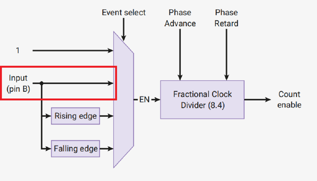
Modes 2 and 3 may be referred to as edge-triggered modes.
These modes can be set in the DIVMODE field of the CSR register of the PWM channel.
In free-running mode, pins A and B are both output pins.
In any other mode, pin B becomes an input pin and is used to control the counter.
Registers relating to the output of pin B will be ignored.
By allowing the PWM channel to run for a fixed amount of time in either level triggered or edge-triggered mode.
This can be used to measure the duty cycle or frequency of the input signal.
It is important to note that at this stage MICROPYTHON can only be set to the default auto-run mode.
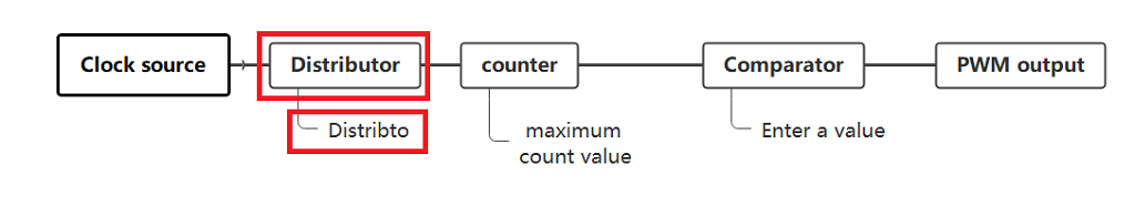
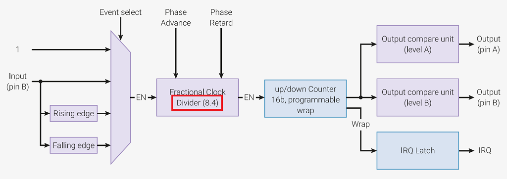
Now comes the second station of the crossover.
Each PWM channel has a separate fractional clock divider and the divider parameters are stored in the DIV register.
This is an 8-bit integer, 4-bit decimal clock divider which reduces the input frequency to 1/256.
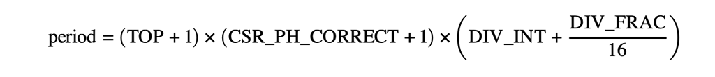
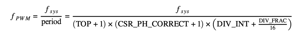
A simple derivation gives the formula for calculating the PWM period and the PWM frequency.
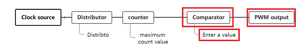
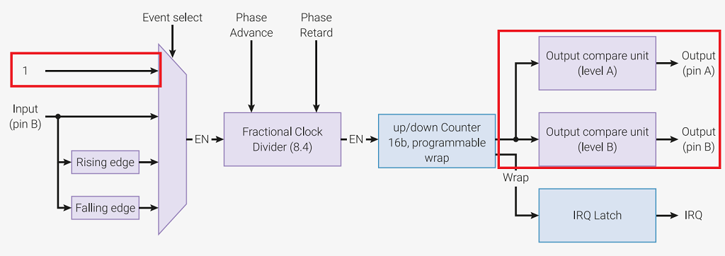
Coming to the third and fourth stop of the PWM.
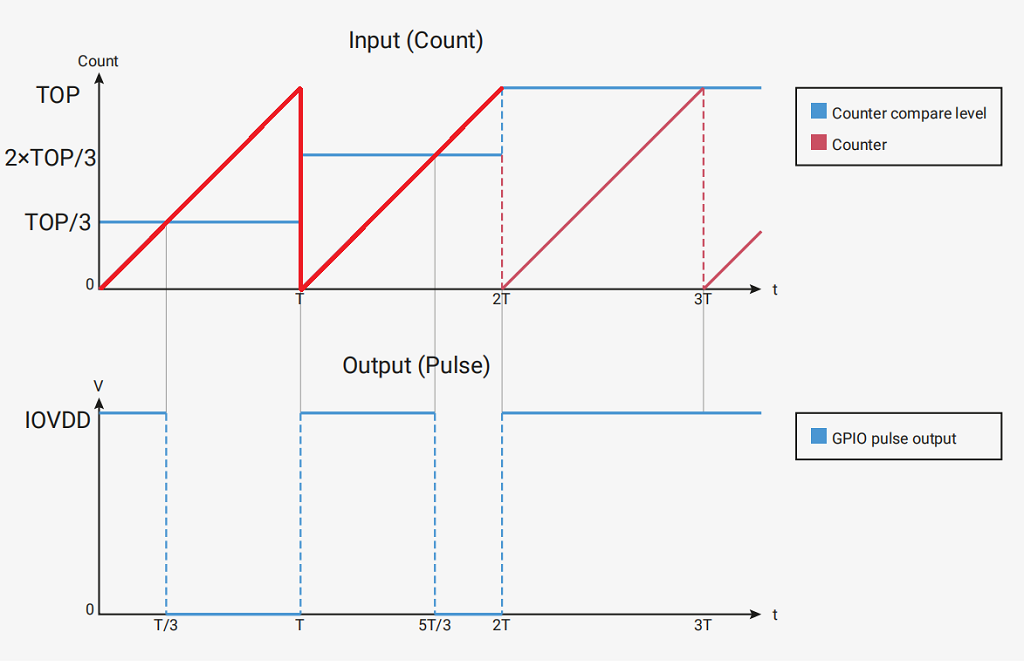
We can see that the PWM output is achieved by constantly comparing the counter value with the input value (CC register).
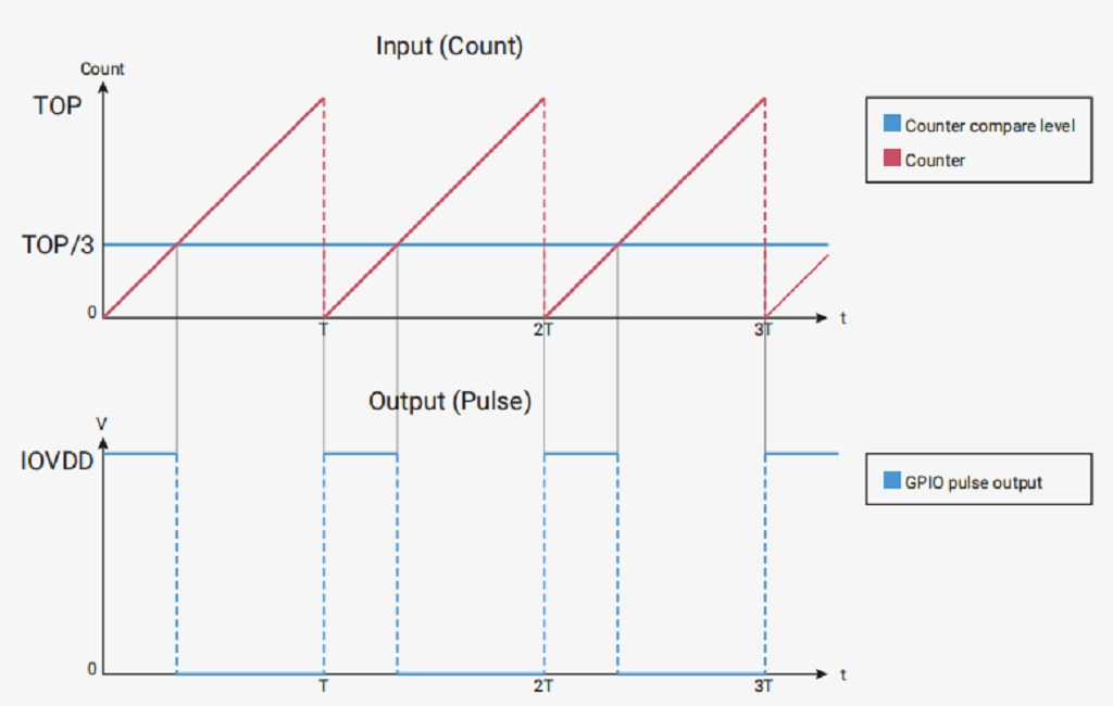
So we will explain the counter and the comparator together.
If the current count is less than the CC register, the counter goes high, if not, it goes low.
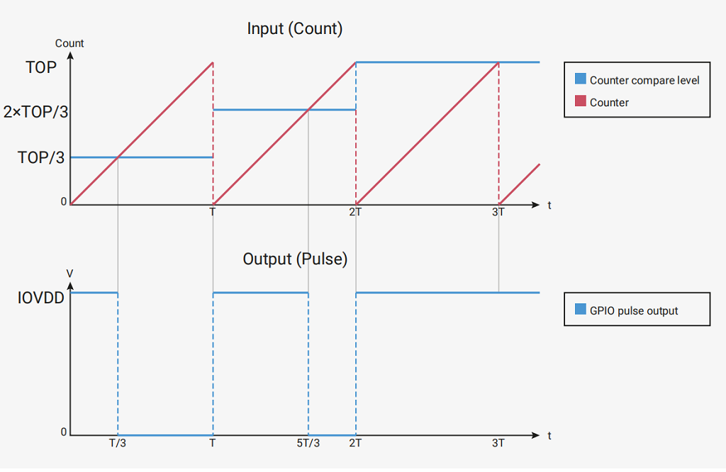
The ratio of the time taken up by the high level to the whole cycle is called the duty cycle.
The count period is controlled by the TOP register because the counter and the TOP register are 16 bits in size.
So the maximum period is 65536 cycles.
By default, the PWM counter counts up until it reaches the value in the TOP register and then resets to 0.
The RP2040 also provides a phase correction mode.
The counter starts counting down after reaching the top until it reaches 0 again.
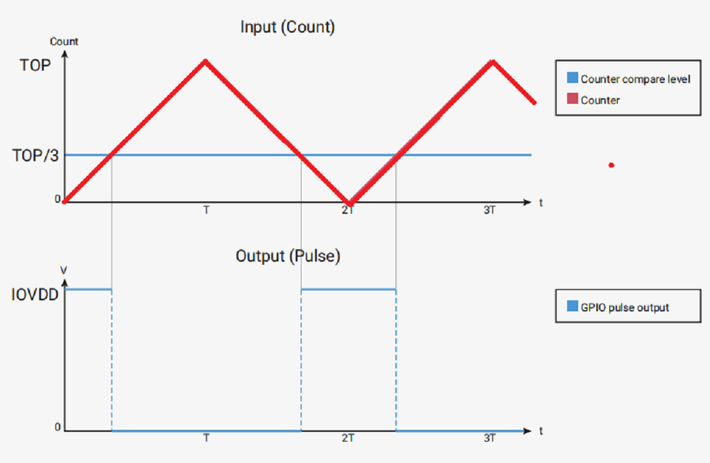
The pulse is therefore always centered at a certain point, regardless of the duty cycle.
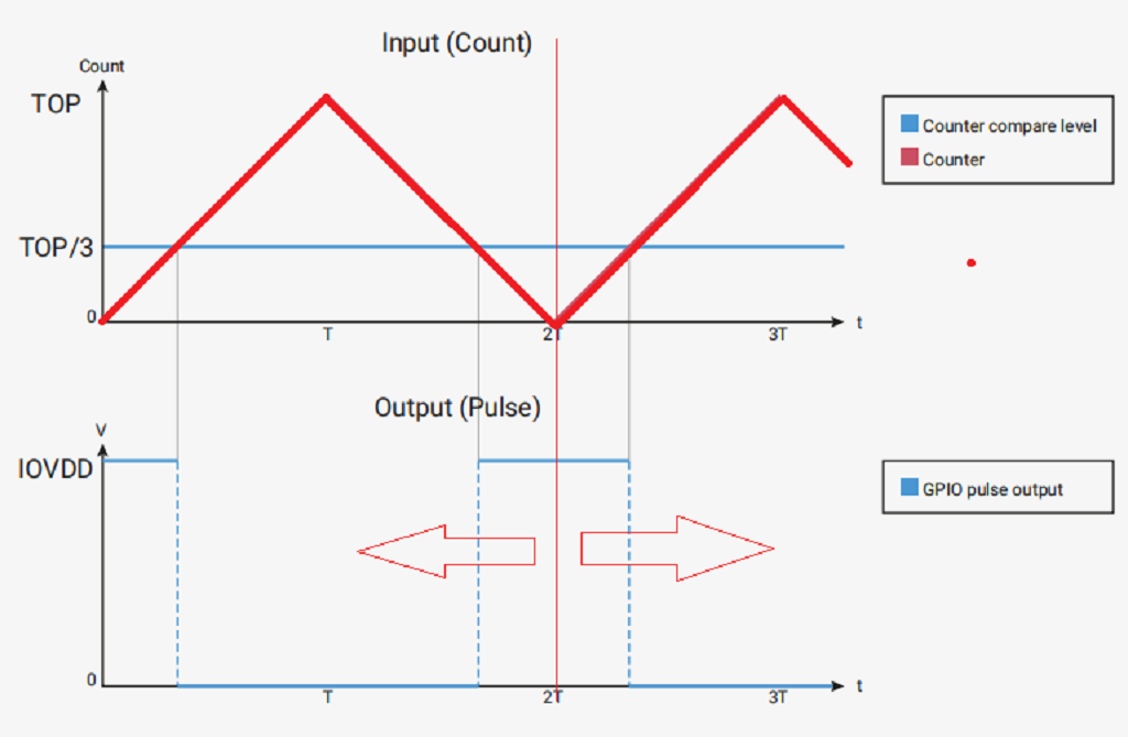
Note: When the phase correction mode is on, the output frequency is halved.
That’s it for the theoretical part of PWM, let’s move on to the next part.
This function is a PWM object constructor that specifies the GPIO to be reinitialized and set to PWM output.
The first parameter pin is the Pin object that was explained in the previous tutorial.
The deinit function is a counter-initialization function that clears the initialization and stops the PWM output.
The freq function is a PWM frequency setting function.
The parameter value automatically calculates the divider parameters and TOP register parameters, mentioned above is the TOP register, which determines the maximum count value of the counter.
The duty_u16 function is used to set the duty cycle.
The first parameter value is automatically calculated and assigned to the CC register. When the counter value is less than the CC register, the PWM outputs high and vice versa.
The duty_ns function is used to set the duration of a cycle of high output.
The parameter value is the high-level time, in ns.
We now have a general understanding of the functions and objects related to PWM.
Python
from machine import Pin,PWM
import utime
#Set GP1025 output pvm
LED= Pwa(Pin(25))
#Set pwmnfrequency to 1000Hz
LED.freq(1000)

LED_duty = 0
LED_direction = 1

while True:
    LED_duty += LED_direction
    if LED_duty >= 100:
       LED_duty = 100
       LED_direction = -1
    elif LED_duty <= 0:
        LED_duty = 0
        LED_direction = 1
    LED.duty _u16(int(LED_duty * 6S5.36))
    if LED_duty%5 == 0;
        print(LED_duty)
    utime.sleep(0.01)
See the first two lines that introduce the Pin, PWM class, and time class in the machine.
Python
from machine import Pin,PwM
import utime
The PWM class has been added so that we can use PWM in this way.
Python
#Set GP1025 output pvm
LED= Pwa(Pin(25))
#Set pwmnfrequency to 1000Hz
LED.freq(1000)
Next, we set GPIO25 to PWM output with an output frequency of 1KHZ.
Python
LED_duty = 0
LED_direction = 1

while True:
    LED_duty += LED_direction
    if LED_duty >= 100:
       LED_duty = 100
       LED_direction = -1
    elif LED_duty <= 0:
        LED_duty = 0
        LED_direction = 1
    LED.duty _u16(int(LED_duty * 6S5.36))
    if LED_duty%5 == 0;
        print(LED_duty)
    utime.sleep(0.01)
Here we set LED_duty to 0 and LED_direction to 1.
Then we add LED_duty to LED_direction in the loop and give LED_duty.
If LED_duty is greater than or equal to 100, then LED_direction is set to -1.
If LED__duty is less than or equal to 0, then LED_direction is set to 1.
Then use the duty_u16 function to set the LED_duty to duty cycle by a certain percentage.
and output the value of LED_duty when LED_duty can be divided by 5.
Here we have implemented a PWM initial output duty cycle of 0% increment to 100%.
Then we start decreasing, decreasing to 0% and increasing, and so on and so forth.
In this way, we have completed the programming of the LED breathing light.