In the last -term we have used ADCs and internal temperature sensors to read pin voltages and on-chip temperatures to implement the process of converting analog signals into digital signals. By now, having learned to use PWM and ADC, these set the stage for our Pico:ed to work in different situations.
In this issue, we need to learn how the MCU “speaks”. Since speech requires certain rules or grammar, just as human languages are divided into Chinese, English, German, and so on. Of course, when two people speak, they need to specify the language in which they will communicate.

It is impossible to communicate when two people do not speak the same language.

If the MCU wants to talk, it needs to agree on certain rules. These rules are called communication protocols.

The most common communication protocols used in MCUs are UART, I2C and SPI.

Most of the microcontrollers on the market today will have hardware peripherals.
Why do we emphasize hardware peripherals here?
Because these communication protocols are relatively simple and we can also use software to emulate these protocols to achieve the communication function.

Explain about UART, the full Chinese name is Universal Asynchronous Transceiver.

It is also known as a serial port, which defines two data lines and enables full duplex transmission and reception.

There are a lot of terms, are you already confused? Here are a few terms in particular.
Serial: this is the term used to describe a communication method that transfers metadata one bit at a time.
The opposite of serial is parallel.
It is used to describe a method of communication in which multiple pieces of metadata are transferred at a time.
Asynchronous means that the two parties do not need a common clock, i.e. the receiver does not know when the sender is sending, so it is important that the message sent has a message to indicate that the receiver is starting to receive, such as a start bit, and that there is a stop bit at the end of the message.
The opposite term to asynchronous is synchronous, which means that both parties have a common clock, often provided by the host computer or the same clock source Full duplex: a term used for communication transmissions.

A full duplex means that the communication allows data to be transmitted in both directions simultaneously.
Half-duplex means that the communication allows data to be transmitted in both directions but not at the same time.
Simplex means that communication allows data to be transmitted in one direction.
The UART works by agreeing on a baud rate for communication and then transmitting the data bit by bit.

Now we see the timing diagram of the UART, where the meaning of each bit is as follows.

The number of data bits can be 4, 5, 6, 7, 8, etc., and constitute a character.
ASCII codes are often used, starting with the lowest bit and relying on clock positioning.

This bit is added to the data bits to make the number of “1’s” even (even parity) or odd (odd parity) to check the correctness of the data transmission.

As the data is timed on the transmission line and each device has its own clock it is likely that the two devices will have a small desynchronization during the communication process so the stop bit not only indicates the end of the transmission but also provides the opportunity to correct the clock The more the number of stop bits, the greater the tolerance of different clock synchronization but also the slower the data transfer rate.

For example, if every 8 bits represents one symbol, the data transmission rate is 1200 characters/second, the baud rate is 1200baud, and the bit rate is 120*8=9600bit/s.

1、Separate FIFO for transmitting and receiving
2、Programmable baud rate generator
3, Standard asynchronous communication bits added on transmit and removed on receive 4, Line feed detection
5, Programmable serial interface (5.6, 7, or 8 bits)
6, 1, or 2 bit stop bit
7、Programmable hardware flow control
Hardware flow control: add two pins RTS and CTS.
RTS for the output signal, used to indicate that the device is ready to receive data, active low CTS for the input signal, used to determine whether the other party can send data, active low Why add these two flow control pins?
Because the two devices communicate through the serial port, the two processing speed is different, which may cause the loss of data such as communication between the desktop and the microcontroller, the receiving end of the receiving data buffer is full at this time also receive the data sent to the possible loss.
This can be effectively avoided by using flow control.
Now that we’ve seen the official box art, does it look dazzling at first glance?
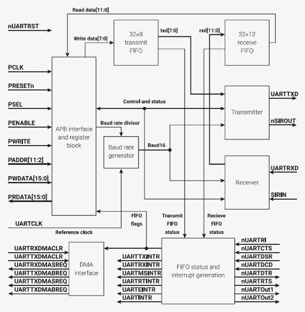
Organizing it into flow charts Here we have divided it into flow charts.
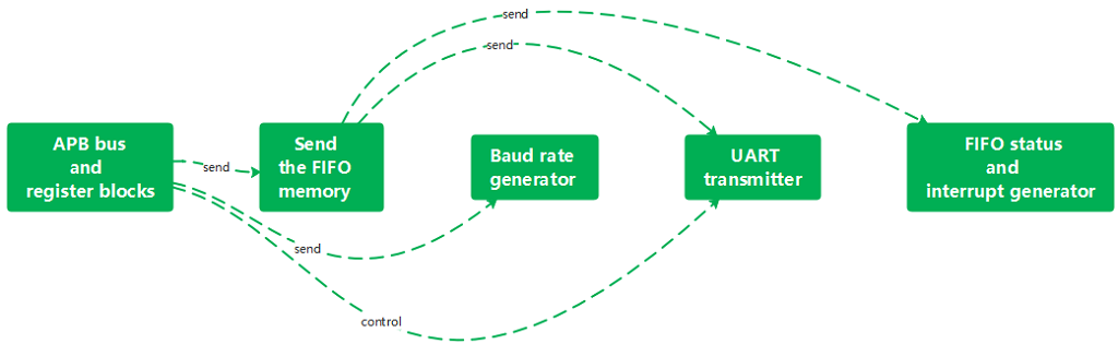
One thing to note here is that we said earlier that the UART is a full duplex, which means that receiving and sending can be done simultaneously.
Here it is just split up for better understanding.
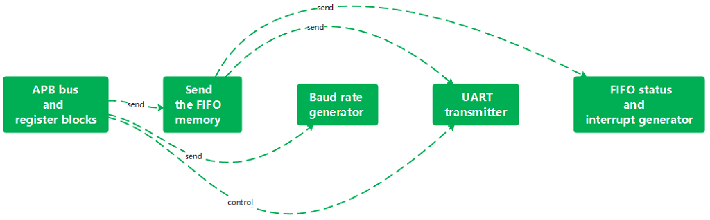
The APB bus can access the status/control registers and store the information to be sent into the transmit FIFO memory.
The baud rate generator takes the baud rate divider from the APB bus and registers blocks to generate the internal clock Baud16
The frequency is 16 times the baud rate.
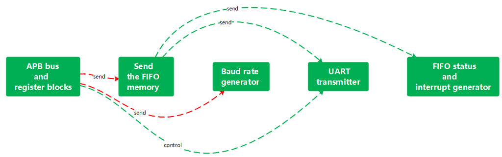
The UART transmitter is controlled by the status/control register and uses Baud16 as the clock source.
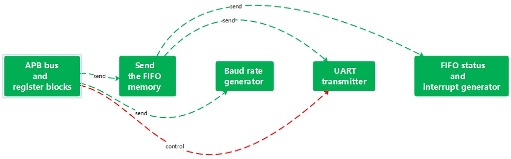
Sends the contents of the transmitted FIFO memory one by one.
The FIFO status and interrupt generators generate the corresponding FIFO flag bits and interrupt signals according to the FIFO memory.
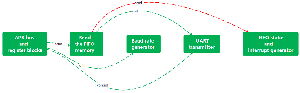
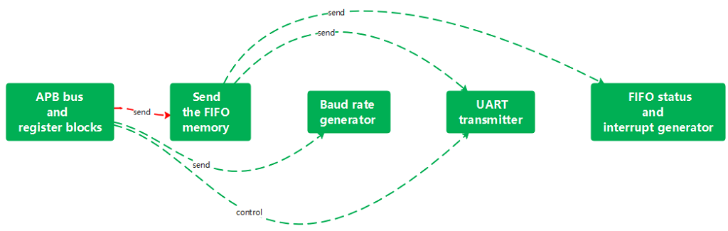
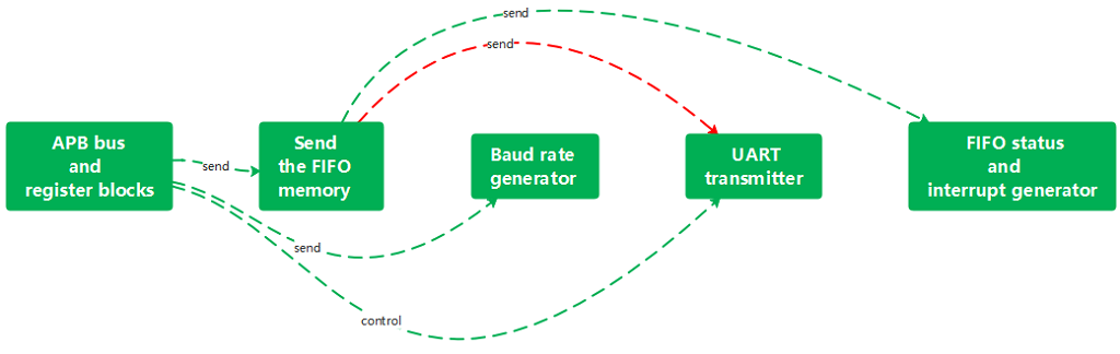
We now see the reception flow diagram.
The UART receiver, like the UART transmitter, is controlled by the status/control register.
The Baud16 is used as the clock source and the received information is stored in the received FIFO memory.
The APB bus can obtain the read value by reading the received FIFO memory.
machine.UART is the constructor of the UART object, which is used to initialize the corresponding channel and pins.
The first parameter id is the UART channel to be used, which can be 0 or 1.
The second parameter baud rate is the baud rate to be used.
The third parameter, bits, is the length of the data bits (at this stage only 8 bits are valid) and the fourth parameter, parity, is whether to use parity bits.
The fifth parameter, stop, is the length of the stop bit.
The sixth and seventh parameters are tx and RX for the transceiver pins, which should be Pin objects.
is used to detect whether there is data in the current receive buffer, and return 1 if there is data in the receive buffer, otherwise, return 0.
UART.read function is used to read a string.
nbytes: if ‘nbytes’ is specified, then read at most this many bytes, otherwise read as much data as possible.
The readline function, which reads a line, ends with a newline character.
The readinto function, which stores the read string in the specified cache.
The buf argument is used to specify the cache.
nbytes is the same as the nbytes argument to the read function above.
Write a function, used to send a string, and return the number of bytes sent parameter buf for the string to be sent write function is used to send a string, and return the number of bytes sent.
sendbreak function: sends a stop status to the bus, pulling down the bus by 13 bits.
Python
from machine import UART,Pin
import utime

uart = UART(0,baudrate=115200,tx=Pin(0) ,rx=Pin(1))
led = Pin(25,Pin.oUT)
uart.write("waveshare Uart Testlrin")
uart.write("Please enter character 0 or 1 to switch the LED on and off\r\n")
while True:
    if uart.any( ) == True:
        buf=uart.read(1)
        if buf == b'1':
            led.on()
            print("LED ON")
            uart.write("LED ON\r\n")
    elif buf == b'0':
           led.off()
           print("LED OFF")
           uart.write("LED OFF\rin")
    else :
        print("Please enter character 0 or 1 to switch the LED on and off")
        uart.write("Please enter character 0 or 1 to switch the LED on and off\r\n")
    utime.sleep_ms(1)
     #machine.reset()
In the first two lines, we have imported the corresponding libraries.
Python
from machine import UART,Pin
import utime
We then initialized UART channel 0 with a baud rate of 115200.
GPIO0 and GPIO1 are used as TXD and RXD pins respectively for UART communication and initialization. GPIO25 is used as an output pin to drive the onboard LEDs.
Python
uart = UART(0,baudrate=115200,tx=Pin(0) ,rx=Pin(1))
led = Pin(25,Pin.oUT)
The corresponding prompt message is then sent via UART.
Python
uart.write("waveshare Uart Testlrin")
uart.write("Please enter character 0 or 1 to switch the LED on and off\r\n")
In the loop, we use any function of the UART class to determine if a message has been received and then use the read function to get the received data.
The read function determines whether the data is character 1 or character 0.
If it is character 1 or character 0, the LED will be turned on or off, if not, the message will be output again.
Python
while True:
    if uart.any( ) == True:
        buf=uart.read(1)
        if buf == b'1':
            led.on()
            print("LED ON")
            uart.write("LED ON\r\n")
    elif buf == b'0':
           led.off()
           print("LED OFF")
           uart.write("LED OFF\rin")
    else :
        print("Please enter character 0 or 1 to switch the LED on and off")
        uart.write("Please enter character 0 or 1 to switch the LED on and off\r\n")
    utime.sleep_ms(1)