The I2C integrated circuit bus, a serial communication bus using a multi-master-slave architecture, was developed by Philips in the 1980s to allow motherboards and embedded systems to connect low-speed peripherals.
The correct pronunciation is “I square C” or “I square C”, while “I two C” is the wrong pronunciation.
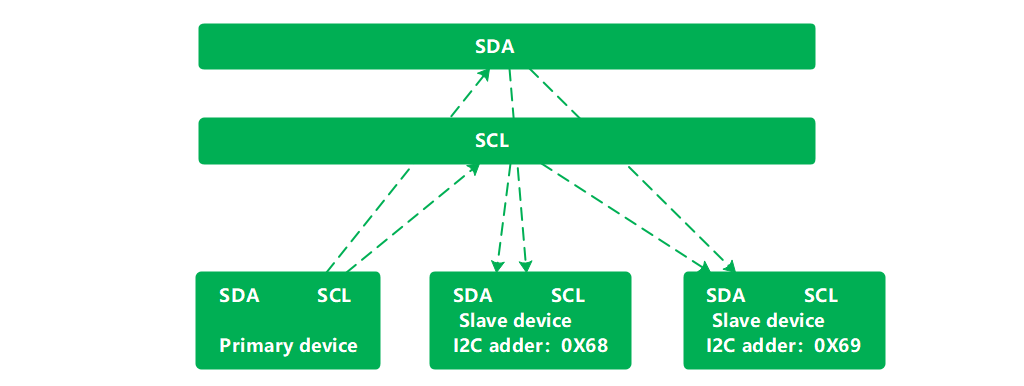
The physical connection is very simple and consists of SDA (serial data line), SCL (serial clock line), and pull-up resistors.
The communication principle is based on controlling the SCL and SDA high and low levels to generate the signals required by the I2C bus protocol for data transfer.
When the bus is idle, SCL and SDA are pulled high on the pull-up resistors and remain high.
The I2C protocol is a serial, synchronous communication protocol, as we can see by its physical connection.
Each device on the I2C bus will have a unique I2C address, some slave devices can change the I2C address – via peripheral circuitry.

This address is used by the master and slave devices to determine which device to communicate with.
The master and slave devices on the I2C bus transmit data in bytes (8 bits) in both directions.
Standard mode:100Kb/s
Fast mode:400Kb/s
Fast mode:1000Kb/s
High-speed mode:3.4Mb/s
Super speed mode:5Mb/s
PS: Devices that only support standard mode are not upward compatible because they cannot support higher transfer rates.
Therefore, they cannot be used in higher-speed I2C bus systems.
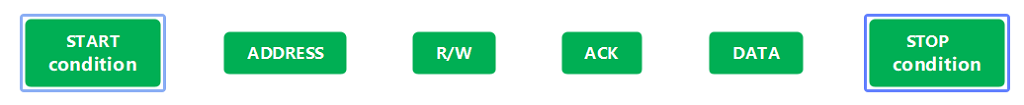
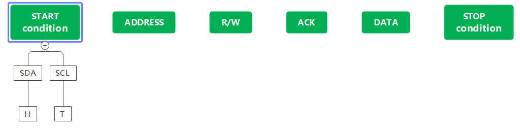
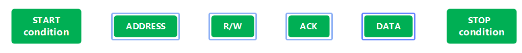
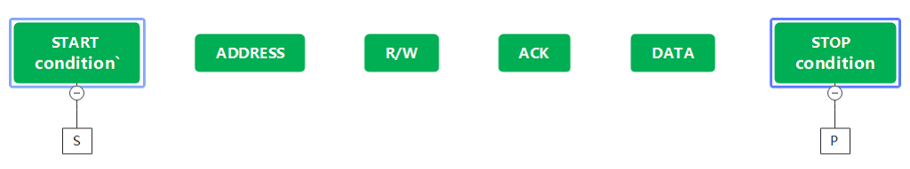
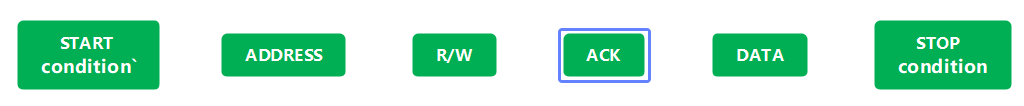
The I2C protocol stipulates that the transmission of data on the bus must have a start signal as a condition and an end signal as a condition to stop the transmission.
When the bus is idle, SCL and SDA are both held high.
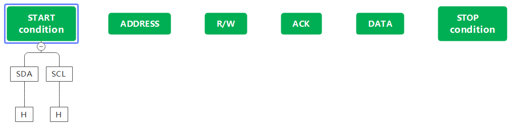
When SCL is high and SDA jumps from high to low, a start signal is generated.
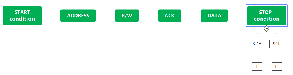
When the transmission ends, SCL is high and SDA jumps from low to high, indicating that a stop condition has been generated.
After the start condition has been generated, the bus is busy and cannot be accessed by other I2C devices because the master and slave devices for this data transfer have exclusive access to the bus.
After the stop signal has been generated, the master and slave devices for this data transfer will release the bus and the bus will be idle again.
Data is transferred in bytes and the master device transfers one data bit on the SDA line for each clock pulse generated on the SCL line.
When a byte has been transferred in ascending order of data bits, the slave device will then pull the SDA line low.
An answer bit is passed back to the master device and only then is a byte considered to have been truly transferred.
Of course, not all byte transfers have to have an answer bit.
For example, if the slave device can no longer receive data (sent by) the master device, the slave device will not return the answer bit.

1. Support master mode and slave mode (default master mode)
2. Support standard mode. Fast mode and fast mode+
3. The default slave address is 0X55
4.10bit address supported in master mode
5.16-bit receive buffer
6.16-bit transmit buffer
7. DMA driver available
8. Interrupt generation is available
I2C object constructor to initialize the corresponding I2C channels and pins.
i2c_id: the I2C channel to use, can be 0 or 1.
scl: SCL pin, should be Pin object (I2C0 default is 9, I2C1 default is 7)
sda: SDA pin, should be Pin object (default 8 for I2C0, default 6 for I2C1)
freq: I2C clock frequency, default is 400Kb/S
The scan slave function returns a list of the 7-bit addresses of all mounted slave devices on the I2C bus.
The read from function is used to read data from the device via the I2C bus and return a byte string.
addr: address of the slave device.
nbytes: the length of the characters to be read.
stop: whether to send an end signal after the data has been received.
The readfrom_into function is an updated version of the readfro function, which specifies that the read data should be stored in an array of characters.
addr: address of the slave device
buf: an array of characters to store the data
stop: whether to send an end signal after the data has been received
The writeto function is used to write data to the slave device.
addr: address of the slave device
buf: send string
stop: whether to send the end signal after receiving the data
The readfrom_mem function is used to read data from the device’s registers.
addr: address of the slave device
memaddr: the address of the register
nbytes: length of bytes to read
addrsize: the length of the register address
The readfrom_mem_into function is used to read data from the device’s registers into the specified character array.
addr: the address of the slave device
memaddr: register address
buf: an array of characters used to store data
addrsize: the length of the register address
The writeto_mem function is used to write data to the registers of the slave device
addr: the address of the slave device
memaddr: the address of the register
buf: send string
addrsize: the length of the register address
Python
from machine import I2C,Pin

i2c = I2C(id=1,scl=Pin(7),sda=Pin(6),freq=100_000)
if len(addr_list) == 1:
     who = i2c.readfrom_mem(addr_lst[0],0x00,1)
     # Identify ICM20948
     if who[0] == 0xEA :
        print("Just a ICM20948 connected")
    else :
        print("Have a device connected but it is not ICM20948")
# Nothing connected
elif len(addr_list) == 0:
        print("Nothing connected")
# More than one device is connected
else :
        print("More than one device is connected")