The so-called line follow car means a car follows a black line on the white(or light color)ground. Because the black line and white ground have different reflections to the light, the car can drive according the the strength of the light reflection received. Today, we are going to make a line follow car with micro:bit.
In this project, we will mainly use micro:bit and motor:bit. More details about micro:bit, you can read:Start Your Micro:bit Programming Trip More details about motor:bit, you can read:Elecfreaks Motor:bit User Guide
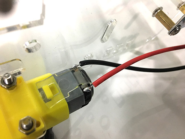
Weld motor cables. If there are no lead cables on your motors, you have to weld cables for them.
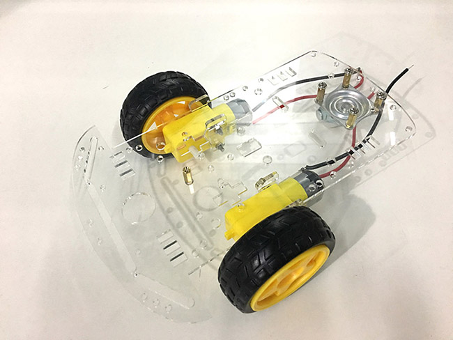
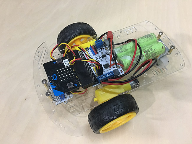
Within the package of car chassis, there is a drawing for instruction. You can refer to its instructions and assemble the chassis. Once finished, you will see the chassis below:
Fix motor:bit to the chassis of the car.
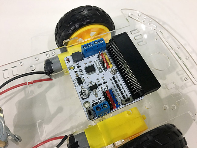
Plug the two groups of motor cables into connector M1 and M2.
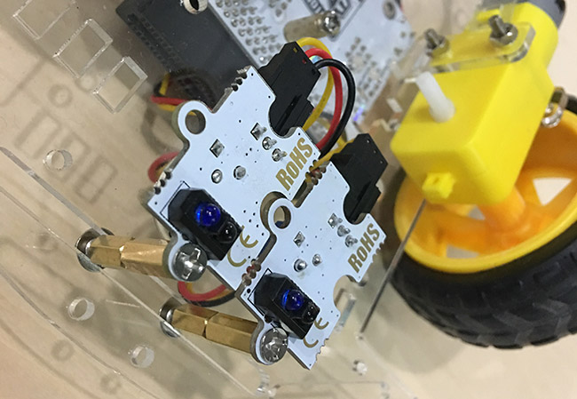
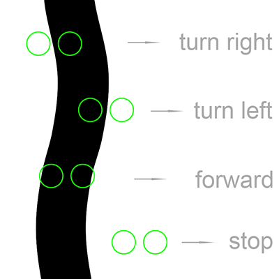
Install line follow modules and pay attention to their space. In this project, the space of two line follow modules is about or a little bit smaller than the width of the black adhesive tape. Plug the two line follow modules into P4 and P5 separately.
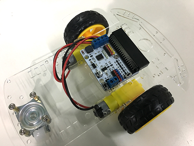
Connect with 6~12v DC power supply. Here, we have connected 2 segments of 18650 batteries in parallel, and then plugged a micro:bit.
You can see the whole electric circuit in the below: 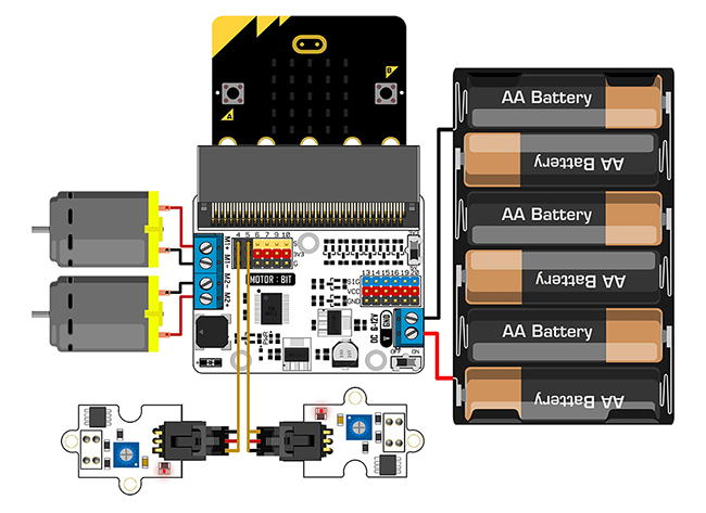
Draw a trace on the ground with a black adhesive tape. You have to pay attention to the width of the tape. It is a little bit bigger than the width of two line follow modules.
Please download the program below into micro:bit, watch out the rotating directions of the two motors. According to this program, the motors should both move forward. If one motor in the opposite direction, you have to change the cable connection of the motor in error and reconnect motor:bit.
Adjust line follow module to enable recognition of black lines and white base board. If the recognition is not available, you can adjust the sensitivity of the potentiometer on the module.
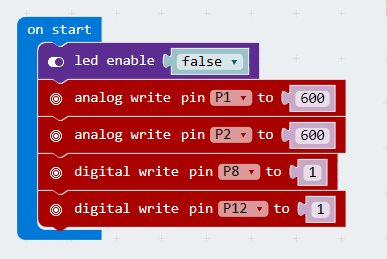
Since hardware connection is completed, we can start to edit our program now. In this case, lots of pins and micro:bit built-in LED dot matrix can be used repeatedly, so firstly we should turn off the LED screen. 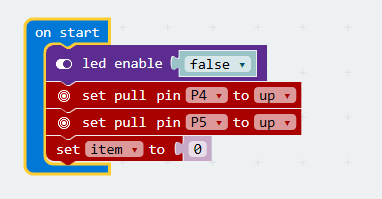
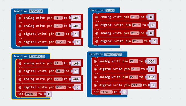
Write program for forwarding, stopping, turning left and right. Control the rotate speed of the motor through analog wite. Bigger value it has, the motor rotates faster.
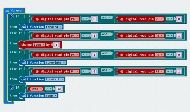
According to the logic below, write your main program of line follow project.
You can click Downloaddirectly to save the code into micro:bit.
Make A Cool Micro:bit Hovercraft Together Elecfreaks Motor:bit User Guide