

Snake on the BBC micro:bit
January 5, 2019
Micro:bit Basics for Teachers Part 3: MicroPython
January 5, 2019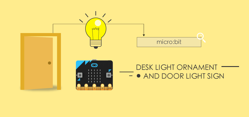
This tutorial will show you how to program and build a desk ornament that lights up. These lights change colors over the course of an hour. You will also learn how to program and build an accompanying door sign that lights up. You can use the door sign as decoration or as a way to let others know you are on the phone or busy 🙂 https://youtu.be/pM8fj86rxj8
Step 1: Gather Supplies
You will need: TECH
- Two battery packs
- Two micro:bits – if you get the micro:bit go bundle, it includes a battery pack
- 1 meter Neopixel LED light strip
- Alligator clips
- Jumper wires
- Access to soldering iron and solder (optional – but best for long term use)
AESTHETIC (you can use different materials for a different looking desk ornament or door sign)
- Duck Tape
- Thin wood for laser cutting – I found some at my local craft store
- Cardboard gift box – I found this at my local craft store
- Glass light bulb shaped cup
- Shadow box
- Styrofoam
- Frosted spray paint for glass light bulb

Step 2: Programming the Desk Ornament Light
https://youtu.be/U94AM50ygws Desk ornament code – created using Makecode.org I programmed the Micro:bit for the desk ornament using Makecode.org’s block-based programming platform. To use makecode.org, you can click on the link to the desk ornament code above and then select edit. This will take you into makecode.org’s editor where you can begin using this code. The video above walks through what each part of the code does, so you can easily customize it for your project. Some ideas for customizing your code are changing the time intervals or changing the color of the lights. Time intervals are currently at every ten minutes the light color will change. You can change the light colors to any RGB color. Once the code is how you want it, download the code and upload it to one of the Micro:bits. For help, please see Makecode.org’s documentation on uploading code to the Micro:bit. Tips You can use smaller scale numbers to test your code in the Makecode.org simulator, which also simulates the neopixel light strip. If changing the time intervals, use an online milisecond to minute converterto help figure out your time in miliseconds.
Step 3: Programming the Door Sign Light
https://youtu.be/qW42zgY9asE Door sign code – created using Makecode.org I programmed the Micro:bit for the door sign using Makecode.org’s block-based programming platform. To use makecode.org, you can click on the link to the door sign code above and then select edit. This will take you into makecode.org’s editor where you can begin using this code. The video above walks through what each part of the code does, so you can easily customize it for your project. Some ideas for customizing your code are changing the color of the lights in your door sign. Once the code is how you want it, download the code and upload it to one of the Micro:bits. For help, please see Makecode.org’s documentation on uploading code to the Micro:bit. TipsYou will need to have the door sign code uploaded onto the Micro:bit used for the door sign and the desk ornament code uploaded onto the Micro:bit used for the desk ornament in order to test this code. If your code is not working, make sure you’ve set both Micro:bits to “radio set group 1.” This is like setting the radio frequency and will make sure your Micro:bits can communicate to each other.
Step 4: Testing the Tech
Now that your code is completed, you can test it with your Micro:bits and LED strips. Before doing this, you will need to prepare your LED strips and connect the Micro:bit with the LED strip. PREPARING YOUR LED STRIPS I found that it is suggested that the Micro:bit only powers 8 Neopixel lights at a time. You’ll need to cut your strip, so there are only 8 lights on it. There is a scissor icon above each section of copper signifying where you can cut your LED strip. Once you have two LED strips of 8 lights (one for your desk ornament and one for your door sign), you’re ready to connect the Micro:bit to the LED strip for testing. 
CONNECTING THE MICRO:BIT WITH THE LED STRIPTo test your Micro:bit code with your LED strip, you can use alligator clips to connect the two components. You’ll need to do this for each Micro:bit and LED strip.
- Connect one side of your first alligator clip on the pin number you assigned your LED strip to (in my code this was pin 0). This sends your code to the LED strip.
- Connect the other side of your first alligator clip to to Din copper piece on the LED strip. Make sure it is NOT Dout. The arrows on the LED strip should be going to the right.
- Connect one side of your second alligator clip to the 3V pin on your Micro:bit. This pin powers the LED strip???/li>
- Connect the other end of your second alligator clip to the 5V copper piece???/li>
- Connect one side of your third alligator clip to GND on your Micro:bit. This is your ground.
- Connect the other side of your third alligator clip to GND on the LED strip.

TEST YOUR CODE Now that your technology is connected, you can press the buttons on your desk ornament Micro:bit to see if your LED strips are lighting up. TipsReasons your LED strip might not be working: If you are using more than 8 LED lights to one Micro:bit, you might not have enough power. Double check that your alligator clips are connected to the correct sources. Make sure your alligator heads on the LED strip are not touching.
Step 5: Assembling the Tech
https://youtu.be/F7tfMOn8YT0 Now that you know your tech is working, you can solder jumper wires to the LED strip. Soldering jumper wires will make for a more reliable connection between the Micro:bit and LED strip as well as make sure the copper on the LED strip doesn’t get damaged from the alligator clips. 
Once the jumper wires are soldered to the LED strip, you can connect the alligator clips to the end of the jumper wires instead of directly to the LED strip. 
Tip Some Neopixel LED strips will come with an end like the one in the video for this step. If yours has this end, you can either cut it off or choose not to solder. If you choose not to solder, you will need to insert a jumper wire into the hole that is above the white (or Din) wire. You can then connect an alligator clip to this jumper wire and connect your other alligator clips to the pre-connected wires. The video above shows what inserting a jumper cable into this hole looks like.
Step 6: Assembling the Desk Ornament
 I’ve outlined the steps for how I made my desk ornament. This part of the project could be 100% customized though to make a different looking desk ornament. 1.Use the frosted spray on the glass light bulb, so the light bulb is not see through. You might need to do a couple coats. 2.Cut a hole in the cardboard box. This hole is where you can place your lightbulb and is also where the wires will travel through. Make sure to measure the bottom of your light bulb so it is a snug fit. 3.Cut a small hole in the back of the box for your alligator clips to come out of. In this project, the Micro:bit acts as a controller, so you need to have easy access to it, which is why mine is on the outside of the box. 4.Laser cut the top wood piece. You will need to measure the circle of your light bulb to make sure the hole you laser cut is big enough. 5.Place the light bulb cap in the hole of the cardboard box. It should fit snuggly. 6.Put your wires through the hole in the light bulb cap, which is in the hole you cut. Your LED strip should be poking out the top with your wires in the bottom of your box. 7.Put the alligator clips through the hole in the back of the box. 8.Connect the alligator clips to the Micro:bit. 9.Place the top wood piece over the light bulb cap and make sure it looks how you want it too. If it does, you can glue the piece down. 10.Insert the LED strip into the light bulb and screw the light bulb into place. 11.Laser cut any additional decorative pieces for the desk ornament and glue them on. You can now test your desk ornament code with the desk ornament assembled. TipsUse duck tape to organize your wires inside your box. Use duck tape to mark your wires as GND, Din, and 3V. The Micro:bit drains battery power even when nothing is on, so you will want to be able to easily access the on/off switch on your battery pack.
Step 7: Assembling the Door Sign
 I’ve outlined the steps for how I made my door sign. This part of the project could be 100% customized though to make a different looking door sign. Laser cut what will be the front of your door sign. Make sure that light can come through your design Assemble your technology inside the shadow box and behind the piece that was laser cut, so you can’t see it from the front. I used duck tape to organize my wires and keep everything in place Use a piece of styrofoam to press the laser cut piece to the front of the shadow box. This makes it so you do not have to glue this piece to the glass, which could ruin the aesthetic Put the back of the shadow box on. This will press on the styrofoam keeping the laser cut piece in place. Keep the battery pack outside of the shadow box. The wires will run out from the side of the back Attach the Micro:bit’s battery pack to the back of the shadow box. The Micro:bit drains the batteries even when not being used, so this will make it easier to access the battery pack’s on/off switch You can now test your door sign code with your desk ornament’s Micro:bit controller.
Step 8: Have Fun Using!
You can now use your desk ornament as a fun way to see how time is progressing and your door sign either as decoration or to let others know that you’re on the phone or busy :). This article comes from Instructable. Our facebook: https://www.facebook.com/ElecFreaksTech/?ref=bookmarks Twitter: https://twitter.com/elecfreaks