Why we need breakout board for micro:bit? In the following article we are going to show you the answer for this question.
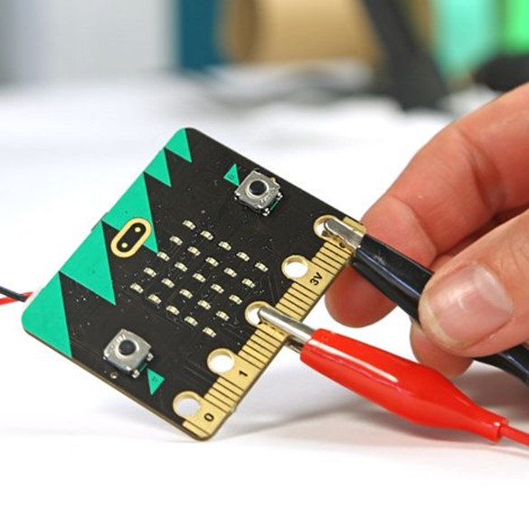
We can take out a micro:bit board and watch it closely. We all know the side pin on BBC Micro:bit board can lead to the input signal or generate control signal with special interface. As for pins of 0/1/2/3V/GND, we can use alligator clip to lead signal. But other pins are too close to lead, which is obviously presented on micro:bit board. Usually the voltage of micro:bit is 3.3V while other modules (like LED digital tube module, IIC LCD module, etc.) connected to it require 5V power supply and 5V TTL voltage to work properly. To solve the above problems, we have invented Micro:bit Adapter.
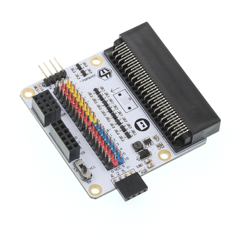
Elecfreaks Micro:bit Breakout Board can completely match with BBC Micro:bit pins. Plug our breakout board into BBC Micro:bit, you will find it is much more convenient to lead.

Features of Elecfreaks Micro:bit Breakout Board:
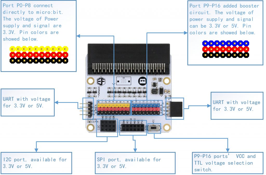
Extended PGIO port from P0 TO P16;
There are pins for VCC and GND beneath each I/O port with different colors for your recognize. You can connect breakout modules conveniently. The arrangement of footers are fully compatible with OCTOPUS series products.
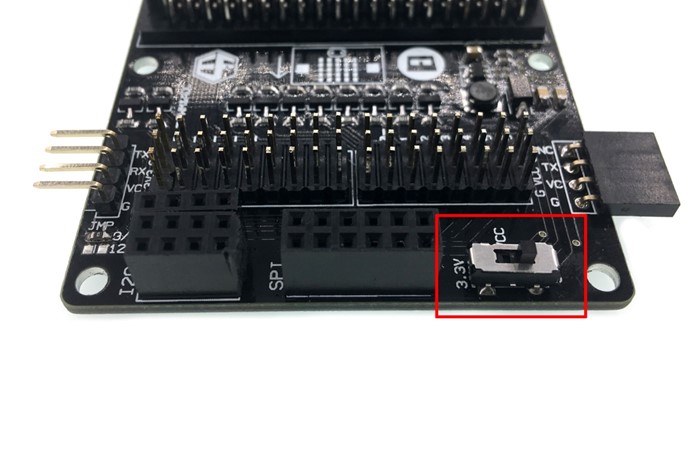
Booster module added enable you to select VCC signal of P19 to P16 between 3.3V and 5V at will.
Lead UART port, I2C port and SPI port. Among these ports, I2C port can connect 3 road I2C devices while SPI can connect 2 road SPI devices.
Two Micro:bit Adapter can connect each other directly to do serial port communication.
The main feature of this Elecfreaks Micro:bit Breakout Board lies in the function of switching power supply. You can remain the original 3.3V voltage while setting the voltage of partial I/O serial ports to be 5V. With this function, we can extend the usage of 5V electronic modules like 4 bits digital tube module. On the other hand, by slide a switch only, we can make it compatible with 5V serial port communication devices. You don’t have to add a voltage switching circuit or a resistance. This breakout board greatly minimized the difficulty of operation so that you can pay more time and energy to programming and creation.
In the following passages, we are going to show you the voltage change of Micro:bit with an oscilloscope.
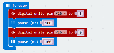
First of all, we have to do a small program with purpose to make P16 lead out a square wave on the oscilloscope. Then download the code into Micro:bit.
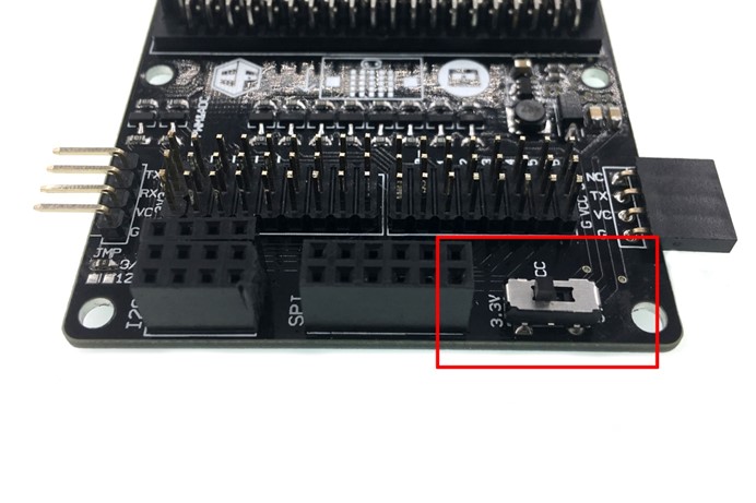
Slide VCC voltage selection switch to 3.3V.
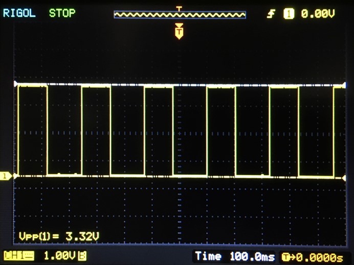
Look at the oscilloscope for the voltage of P16.
Then slide switch to 5V.
Here’s the result of testing P16 with 2 different voltage channels:
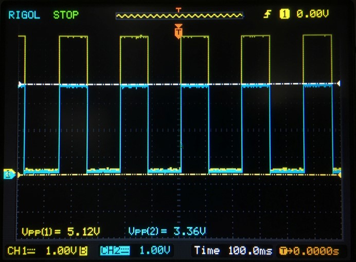
We can see from the oscilloscope that before switching, I/O port voltage is 3.3V; after switching, the voltage becomes 5V. Exchange between 2 different voltage channels are so easy that you only have to slide a switch. Isn’t it very cool?
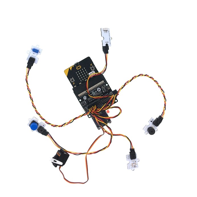
Elecfreaks Micro:bit Breakout Board is fully compatible with OCTOPUS series products.You can connect Octopus series products to micro:bit easily and fast just the same with Freaduino. With the guidance of color, you do not have to worry about connect wrong. Look, the picture below, isn’t it looks like a big octopus?
As for students in the doorstep of learning program, complicated circuit design will be difficult for them and greatly minimize the interest of learning. What students need most at this time? It is encourage and proper guidance. We invented this Elecfreaks Micro:bit Breakout Board aiming to help students use micro:bit as easier as possible and create their own programming artworks. And this is the same with the design purpose of micro:bit–make kids enjoy the happiness of programming and creation.