

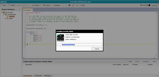
Light Micro:bit with Mbed
January 9, 2019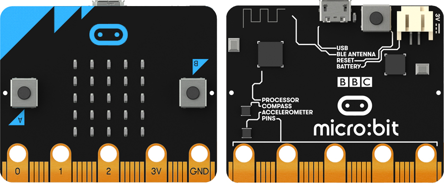
How Micro:bit Works With Octopus???We Made A Raining Alarm Demo
January 9, 2019
1???/span>Introduction
Electronic Alarm Clock Kits is a set of tool for producing an electronic alarm clock. With our guidance, you can make an electronic clock completely by yourself.It is very easy, simple and funny.
The following picture is a completed artwork made with our kits ???/span> 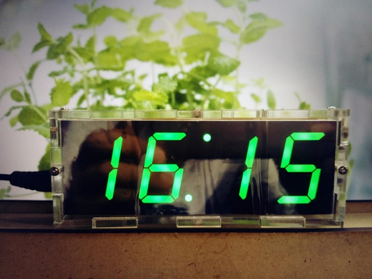 ???/span>Picture 1???/span> Isn’t it beautiful ? If you would like to own an electronic clock like this one, let’s start to learn how to make it.
2???/span>Tools&Materials Needed To make an electronic clock, we have to prepare something first. Then we will need:
-
Adjustable Thermostat Soldering Iron
You can choose 20W internal heated or 25W external heated soldering iron. The head of soldering iron shall be cutting head. If you are a starter, you can choose prong head as well. Normally, we set solder iron temperature value to 350 degrees.
-
Ø 0.8mm Resin-core Lead Solder
-
Materials in the picture 2
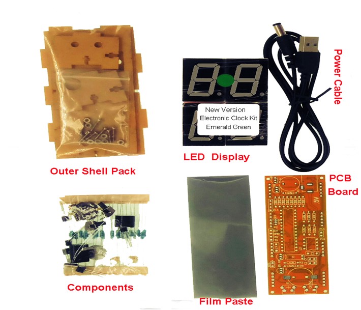
???/span>Picture2???/span>
3???/span>Components Assembly&Installation
Once we gathered all these materials and tools, we can move on to our next step– Assembly&Installation. How to put these materials together to form a clock? This might seems headache . Well, we can start assemble from the inside to the outside of the clock. Let’s begin!
-
Step One???/span>Solder Resistance


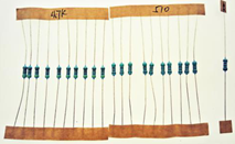
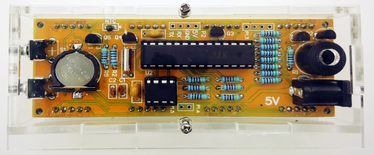
Firstly, we have to use solder iron to solder 10K resistance onto PCB board. ???/span>Resistance has no positive or negative point.???/span>  Note???/span>R2 on PCB board was marked “4.7K” before???/span>now updated to “10K”.
Then solder 4.7K and 5.1k resistance according to the relative marks on PCB.
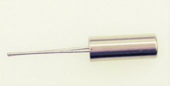
- Step Two???/span>Solder Thermistor
Find thermistor showed in the picture below:

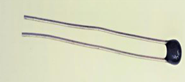
Thermistor was marked NTC on PCB board. Solder thermistor onto the green circle area showed in the following picture. 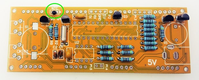 Note:Thermistor has no positive or negative point.
-
Step Three???/span>Solder Ceramic Capacitor

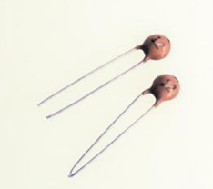
Solder ceramic capacitor onto C1 and C2. 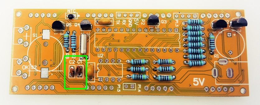 Note:
Note:
-
Ceramic capacitor has no positive or negative point.
-
This component contains ceramic capacitor 12pf.
-
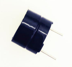
Step Four???/span>Solder Monolithic Capacitor
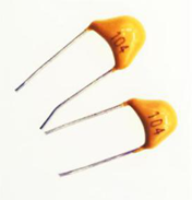
Monolithic capacitor solder on C3 and C4.(See Picture below.) 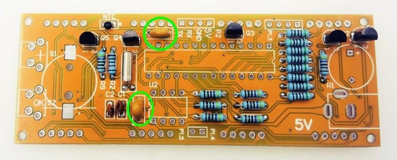 Note:
Note:
-
Monolithic capacitor has no positive or negative point.
-
This component contains monolithic capacitor 0.1uf.
-
Step Five???/span>Solder Crystal Oscillator
 Solder crystal oscillator to Y1 marked on PCB board.
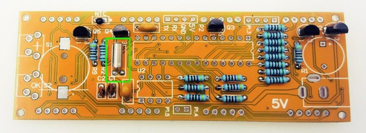
-
Step Six???/span>Solder Triode

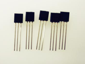
Electronic clock adopt 8050 Triode marked Q1-Q5 on PCB board. 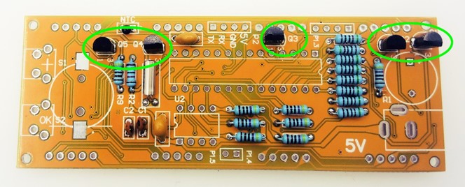 Note: Triode must solder in the same direction with PCB board.
-
Step Seven???/span>Solder IC Socket and Plug IC

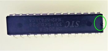
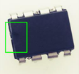
Solder IC socket before plug IC. 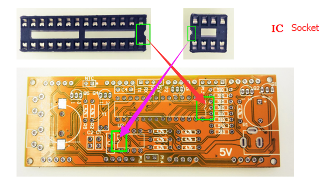 Note???/span> One end of IC socket has a small concave. This end shall in the same direction with the concave mark on PCB board.You can see the above picture for reference.
There is a small concave on both IC and socket.Plug IC into socket according to the direction of concave.Don’t plug IC wrong !
-
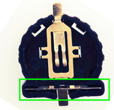
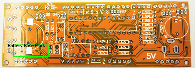
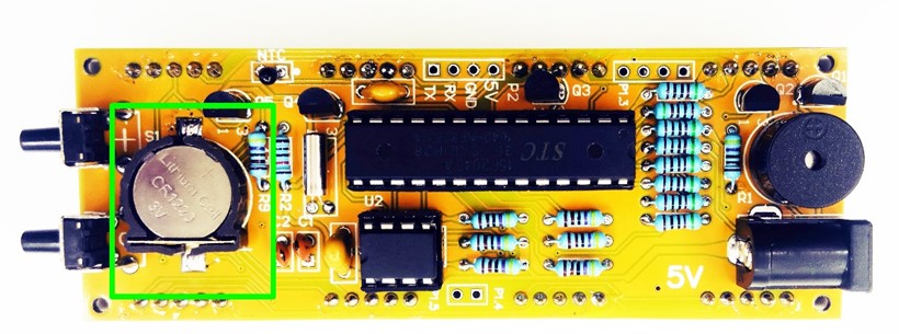
Step Eight???/span>Solder Battery Base
 Note:
Note:
-
Battery base belongs to surface mount type. Before soldering, you have to add tin to a side of solder plate.
-
Battery base has positive and negative point.
-
 The mark for battery base on PCB board has a horizontal line. When soldering, you have to make the iron plate of battery base mounted on the line marked on PCB.

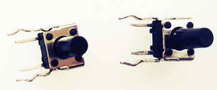
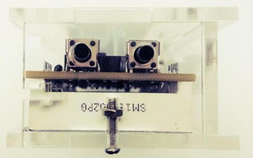
 You can solder microswitch according to the picture above.
-
Step Ten???/span>Solder Buzzer

Solder buzzer onto the green circle area pointed out in the picture below. 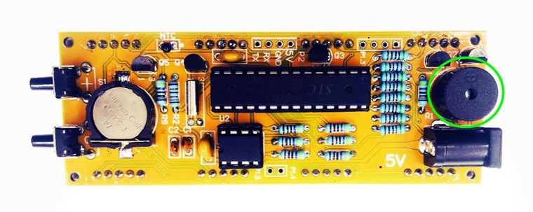 Note:
Note:
-
Buzzer has positive and negative point.
-
Usually, you can see the positive point marked.
-
The pins of buzzer are comparatively longer.
-
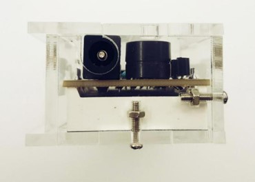
Step Eleven: Solder DC Socket

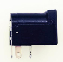
DC socket is the main power supply port of electronic clock. You can solder DC socket according to the picture below. 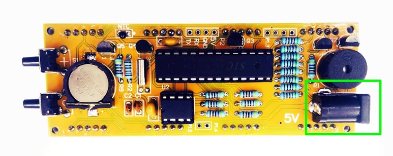
-
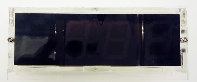
Step Twelve???/span>Solder LED Display
Before soldering, we have to test LED display first. Supply power to LED display and check the number showed on the screen. If it works well, then you can start soldering. 
 Note: The third number shall be placed upside down.
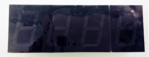
Once you have completed soldering. Don’t forget to paste film paste! Note: Originally, there is a protection film on the surface of LED display and both side of film paste. Before pasting film, you have to tear down the original protection film on the surface of LED display and backside of film paste.The backside of film paste is adhesive, you can paste it on LED display directly. Then tear down the protection film on the surface and press it with a small cloth for cleaning the surface.
-
Step Thirteen: Outer Shell Installation
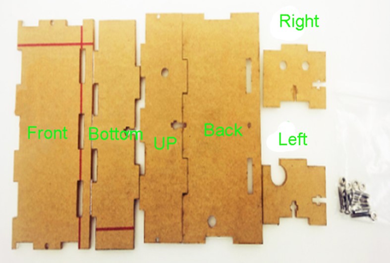
 Unpack outer shell pack before installation. The place it according to the picture showed below.
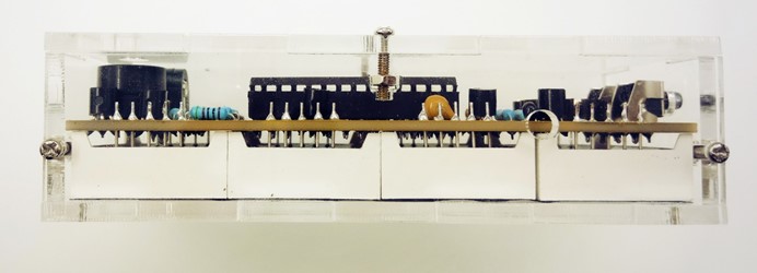
UP
Bottom
Left Right
Front
Back
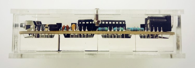
After these parts assembled with PCB board, we have finished installation of electronic clock.
4???/span>Test & Settings
- Test
After installation completed, you have to reset circuit so that it can work properly. You can do it according to the following steps???/span>
- Cut off power supply and press functional key and “+” key at the same time.Then supply power again and release the two keys. It will display “7:59”.
- 5 seconds latter???/span>it will display “8???/span>00″. This indicates successfully reset.And then buzzer alarms.Press “+” key, the alarm will stop.(Or you have to wait one minute before the alarm automatically stops.)
- Temperature Display???/span> Every 30 seconds it will display present temperature.
- Hour Adjustment???/span> Press “OK” key(functional key)???/span>then hour digital tube display will start to flash. Press “+” key to adjust hour.
- Minute Adjustment???/span> Press “OK” key,then minute digital tube display will start to flash. Press “+” key to adjust minute.
- Alarm Clock Hour Adjustment: Press “OK” key(functional key)???/span>then hour digital tube display will start to flash. Press “+” key to adjust hour.
- Alarm Clock Minute Adjustment???Press “OK” key(functional key)???/span>then hour digital tube display will start to flash. Press “+” key to adjust hour.
- Alarm Clock ON/OFF: Press “OK” key, then the digital tube display illuminate but not flash. Press “+” key, the signal light on the right bottom corner of fourth number illuminates, which indicates we turned on the alarm clock . When signal light is off, the alarm clock function is closed.
- Round Clock Alarm Set:
- Press “OK” key,hour digital tube starts to flash. Press “+” key to adjust the beginning time of round clock alarm. If you adjust it to the number “7”, then it alarms at 7 o’clock in the morning.
- Press “OK” key again, then minute digital tube starts to flash. Press “+” key to set a terminal time for round clock alarm. For example, if you adjust it to the number “23”???/span>then from 8:00 am to 22:00pm you will hear round clock alarm.
- Press “OK” key to exit. Then you have completed setting.
For more details, you can refer to our User Guide.