


Make A Cool Micro:bit Hovercraft Together
January 7, 2019
Interesting Processing Programming Guidance for Designer6–Custom Functions and Fractal Recursion
January 7, 2019
In previous chapters, we have talked more about how to use code to do shaping instead of knowledge points about color. In this chapter, we are going to explore this aspect of knowledge deeper.
Basic Knowledge About Color
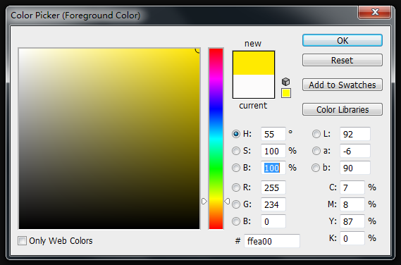
Color, in certain aspect, has surpassed human intuition. Various beautiful colors we seen by our naked eyes are actually consisted of same components. Only with the three light colors of red, green and blue, we can create all colors that can be seen by human eyes through mixture. Mobile screens and computer screens you currently seen are created at the basis of this principle. Red, green and blue are called the three original colors of light. Through the ratio of the three elements, we can assure a certain color. This method of description is also called RGB mode. Among it, red is R, green is G and blue is B. Except for RGB mode, there is another mode called CMYK mode. It is usually combined with printing. In printing, there is three original colors too. However, it is different to the three original colors of light. They are red, yellow and blue separately. Among it, C is for cyan, M is for magenta, and Y is for yellow. Theoretically, only by CMY, we can mix out most colors. But because of the production technique of raw material, we can hardly make the saturation of CMY achieve 100%. If we mix these three colors, we can not obtain black color that is dark enough. So there is an extra K, which is for black printing ink, as the supplement of printing. As for RGB and CMYK, you only have to know that there is a most obvious difference in nature. RGB is plus color mode, which increases brightness by mixing more colors. While CMYK is minus color mode, which increases darkness by mixing more colors. In the picture below, we can visually see the similarities and differences of the two modes. The left picture, we can imagine to be a dark house with three different colors of flashlights turned on. Picture in the right, we can regard it as a watercolor paper after overlapping with three pigments of red, green and blue. 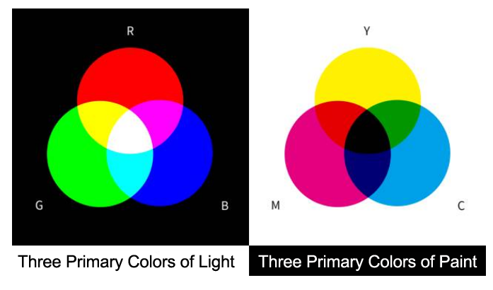 If you want to know its relative relatioships between different color modes more deeply, you can open your photoshop and choose the color picker. Then you can see the color values of a same color under different color modes intuitively.
 In
In
the last, we would like to introduce another common color mode for you, HSB. HSB has no concept of “Original Color”. It is classified according to the feelings of human eyes for colors. H stands for hue, S for saturation, and B is for brightness. Hue represents the color tendency. Every color has a certain kind of color tendency only if it is not balck, white or gray. The most rich color transition area on the color picker is used to indicate hue. Its value in PS ranges from 0 to 360. Saturation means the purity of color. Higher purity brings more vivid color. Its value in PS ranges from 0 to 100. Brightness means the lightness degree of color, ranging from 0 to 100. Compared with RGB mode, the three dimensions of HSB are much more accordant to the feeling of human eyes for colors. Just look at HSB values only, you can generally imagine what kind of color it is.
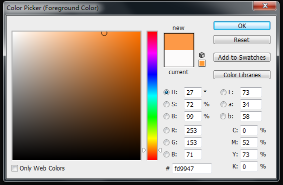
As to the same color, the color value in RGB mode is (255, 153, 71), while in HSB is (27, 72, 100). It is difficult to judge what it will be looks like after mixing the three original colors together if we only look at RGB. But HSB is different. You only have to get familiar with the hues of colors such as red is 0, orange is 30 and yellow is 60, then you will know it will be a comparatively saturated orange color with high brightness and a little bit close to red when H is 27. Next, we will correspond the three dimensions of the two modes into x, y, x in space and
draw a color cubic to do comparison.
RGB and HSB are just different methods to describe colors. We can take address as a metaphor. Suppose if you want to tell other people the position of the Imperial palace, you can say it is at No. 4 of Jingshan Front Street, Dongcheng Area, Beijing. Or you can say it is at 15 seconds, 55 minutes, 39 degrees at North latitude and 26 seconds, 23 minutes, 116 degrees at East longitude. The description method of HSB is similar to the former. If you are familiar with the relative area, you can generally know the position of the address. While RGB may be more accurate, but it is very abstract. HSB mode existed with aims to help us to describe color more conveniently. To display a certain kind of color on the screen, we finnally have to convert it into RGB mode first. In the above, we introduce three color modes: RGB, HSB, CMYK. In the program, you only have to focus on two modes: RGB and HSB. They have their own advantages and their own applications at the same time. If you are familiar with it, it will satisfy your most designing requirements.
Data Type For Storing Colors
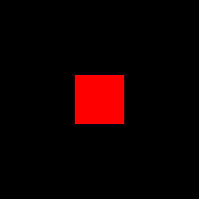
To show colors in program, mostly we use RGB mode in the before. However, only by controlling the three properties, can we display any colors? In computer, it is like this. We have referred before that in Processing, except for R, G, B, we can designate an alpha(transparency) for colors. But alpha is not belong to the component of color. Its existance is to convenient mixture with colors behind. Hence, for computers to describe a certain kind of color accurately, we have to contol the key three variables only. In the following, we start to introduce a kind of data type Color, which is mainly used for storing colors. It is similar to previously referred data types like boolena, int, float. Here, let me keep quite in explaining the actual usage of color first. Imagine this: suppose if we can only use the previously mastered methods to store a certain data, what shall we do? Code Example (9-1): [cceN_cpp theme=”dawn”] int r,g,b; void setup(){ size(400,400); r = 255; g = 0; b = 0; } void draw(){ background(0); rectMode(CENTER); fill(r,g,b); rect(width/2,height/2,100,100); } [/cceN_cpp]
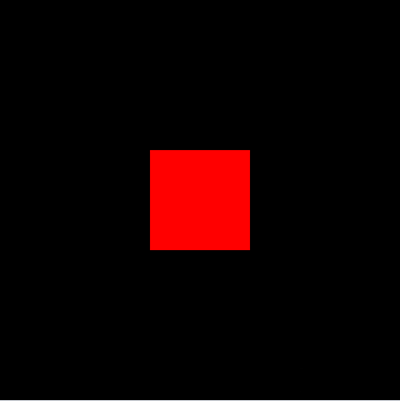
As for colors which has color tendency, we need to create three variables to store data in three color channels of red, green and blue respectively. Later, if we want to invoke this set of color data, we have to write it into fill or stroke. But you will find it is too troublesome to do so because datas are interconnected. If you have idea to pack them in use, it will be more convenient. Therefore, color is created. Code Example (9-2):
[cceN_cpp theme=”dawn”] color myColor; void setup(){ size(400,400); myColor = color(255,0,0); } void draw(){ background(0); rectMode(CENTER); fill(myColor); rect(width/2,height/2,100,100); } [/cceN_cpp]
Same with data types like int, we have to use “color myColor “ at the beginning to create variables. In setup, we use “myColor = color(255,0,0)” to assign value to variable myColor . While function color(a, b, c) rightly represents that this set of data has formed a color type so as to import variable myColor. If you write “myColor = (255,0,0)”, then program will go wrong. In the last, we use fill() to realize the operation of color padding. Function fill() and stroke() are both enable to overlap. According to the quantity and type of parameters, it will have different effects. Importing only one integer variable, which represents it is a color with grayscale only. While importing a variable color, it means the color range will be bigger. You can also import a color variable and an integer variable, change function fill() in the above into fill(myColor,150) , then you can control alpha with the second parameter.
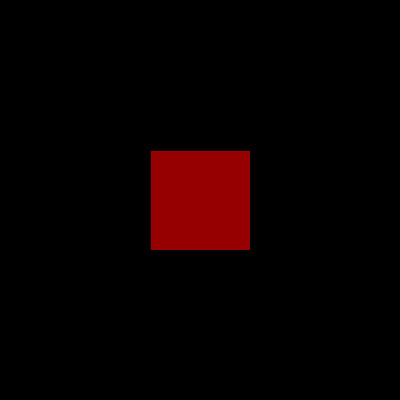
Overlapping Method of Fill
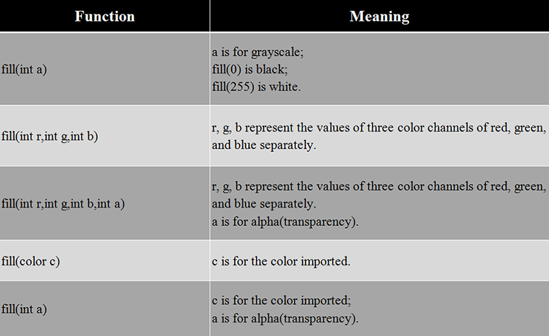
stroke, background have same overlapping method with fill.
Read Channel Value Of Color
In addition to assignments, you can also independently obtain the RGB value in the color variable Code Example (9-3):
[cceN_cpp theme=”dawn”] color myColor; void setup(){ myColor = color(255,125,0); println(red(myColor)); println(green(myColor)); println(blue(myColor)); } [/cceN_cpp]
Result in the console: 255, 125, 0. Function red(),green(),blue() will relatively return back to the value of red, green and blue channel in myColor.
Hexadecimal Assignment
Except for using decimal numbers to show RGB, we can also use hexadecimal.Decimal means increasing 1 when it meets 10. While hexadecimal means increasing 1 when it meets 16. Its relative relationship with decimal is: “0 to 9” correspond to “0 to 9”, “A to F” correspond to “10 to 15” . Picture below is the illustration of the convertion method. 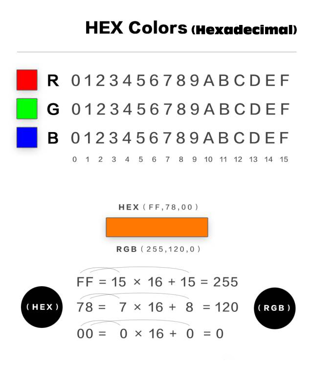
Of course, if we get a set of hexadecimal values like ff7800, we don’t have to convert it by manual. The program will assign values to color variables directly. It is very convenient. We can see many color cards online are all adopt hexadecimal method to display color.

Like design community dribbble, artworks will be attached color palettes. If you see a favorite coloring, you can apply it to the program. Code Example(9-4):
[cceN_cpp theme=”dawn”] color backColor,colorA,colorB,colorC; void setup(){ size(400,400); rectMode(CENTER); noStroke(); backColor = #395b71; colorA = #c4d7fb; colorB = #f4a7b4; colorC = #f9e5f0; } void draw(){ background(backColor); fill(colorA); rect(200,200,90,300); fill(colorB); rect(100,200,90,300); fill(colorC); rect(300,200,90,300); } [/cceN_cpp]
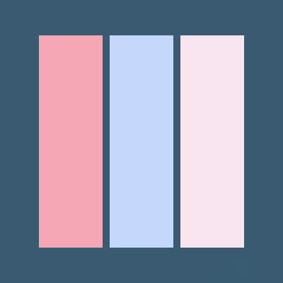
Now, the color is much more comfortable with better effect than inputting values randomly. Add “#” before the hexadecimal color value, then you can assign value to variable color directly.
HSB Mode
Beside RGB mode, next we are going to talk about HSB mode. The following shows the value assignment method of HSB mode. Code Example (9-5):
[cceN_cpp theme=”dawn”] void setup() { size(400, 400); colorMode(HSB); } void draw() { background(0); rectMode(CENTER); for (int i = 0; i < 20; i++) { color col = color(i/20.0 * 255, 255, 255); fill(col); rect(i * 20 + 10, height/2, 10, 300); } } [/cceN_cpp]
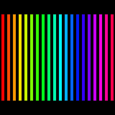
In Processing, in order to switch HSB mode, we only have to add a sentence of colorMode(HSB). The usage of function colorMode() is to shift color mode. If we write “HSB” in the bracket, then it will be set to HSB mode; while we write “RGB”, it will be shifted to RGB mode. What is worthwhile to pay attention is when we write colorMode(HSB) , the defaulted maximum value of HSB is 255. This is quite different to the maximum value in Photoshop. In Photoshop, the max value of H is 360, the max value of S and B are 100. So we need to do convertion.
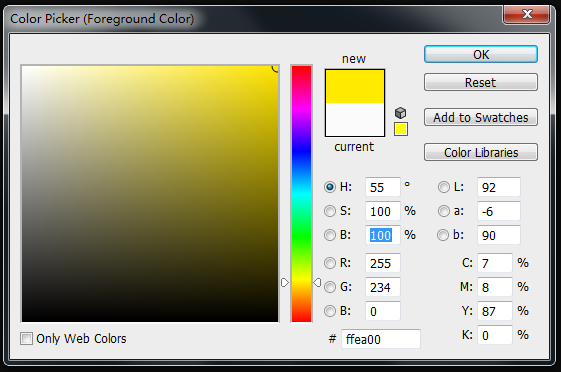
If the HSB value in Photoshop is (55, 100, 100), when converted to Processing , this value should be (55 / 360 × 255,255,255 ), i.e. (40, 255, 255). colorMode() is a function that can be overlapped. In the following, we will introduce it to you in detail.
Overlapping Method of colorMode
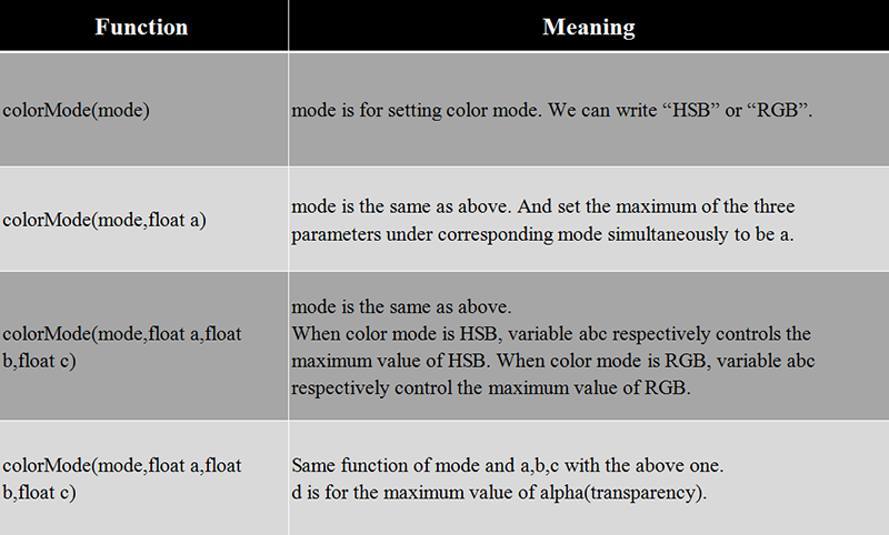
Therefore, if you do not want to convert HSB value in Photoshop manually, you can write “colorMode()” into “colorMode(HSB,360,100,100)”.
HSB Mode Application Case 1
Because RGB mode is not quite convenient to control the changes of hue, at this time, if you wan to control colors more flexibly, you may consider HSB mode. Code Example(9-6):
[cceN_cpp theme=”dawn”] void setup() { size(800, 800); background(0); colorMode(HSB); } void draw() { strokeWeight(2); stroke(int(millis()/1000.0 * 10)%255, 255, 255); float newX, newY; newX = mouseX + (noise(millis()/1000.0 + 1.2) – 0.5) * 800; newY = mouseY + (noise(millis()/1000.0) – 0.5) * 800; line(mouseX, mouseY, newX, newY); } [/cceN_cpp]
When we control H(hues) in stroke, we have used millis(). It will obtain the operation time from the beginning to the present. Thus, as with the time moving forward, the value of H(hue) will increase automatically, then color changes. The unit of millis() is ms. So, when the program runs for 1 second, the return value will be 1000. This will lead to a value that is too big. So we have to divide it by 1000.0. Because we hope that colors will present a periodic circulation, so we have to do modulo operation when we finally write the first parameter in stroke. This can make sure that it will start from 0 again when H(hue) has surpassed 255. Function strokeWeight() can control the thickness of lines. The corresponding unit for parameters within the bracket is pixel.
HSB Mode Application Case 2
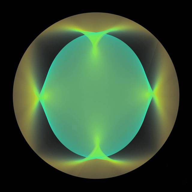
Code Example(9-7): [cceN_cpp theme=”dawn”] int num; // quantity of lines currently drawn float posX_A,posY_A; // Coordinate of point A float posX_B,posY_B; // Coordinate of point B float angleA, speedA; // Angle of point A , speed float angleB, speedB; // Angle of point B, speed float radiusX_A, radiusY_A; // The radius of oval formed by point A in X(Y) axle. float radiusX_B, radiusY_B; // he radius of oval formed by point B in X(Y) axle. void setup() { size(800, 800); colorMode(HSB); background(0); speedA = 0.0009; speedB = 0.003; radiusX_A = 300; radiusY_A = 200; radiusX_B = 200; radiusY_B = 300; } void draw() { translate(width/2, height/2); for (int i = 0; i < 50; i++) { angleA += speedA; angleB += speedB; posX_A = cos(angleA) * radiusX_A; posY_A = sin(angleA) * radiusY_A; posX_B = cos(angleB) * radiusX_B; posY_B = sin(angleB) * radiusY_B; stroke(int(num/500.0) % 255, 255, 255, 10); line(posX_A, posY_A, posX_B, posY_B); num++; } } [/cceN_cpp]
Operation Effect:

Output Picture:
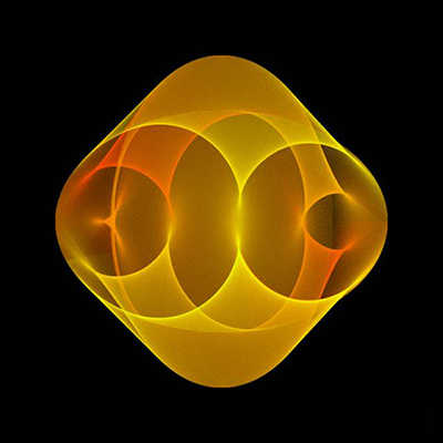
The pattern you seen is produced by a motional line through constant overlapping. The traces of the two end points of the line are two circles separately. Through HSB mode, we have controlled the changes of hue. With the increase of lines, the hue will offset. When massive half-transparent lines overlapped, it will create very rich color gradient. We have embedded a for loop into function draw with aims to use for loop to control the quantity of line. It is equivalent to that we have controlled drawing speed. Increasing the value of judgement condition in for loop, it will increase the drawing seepd. Below is the schematic figure. You can see the movement trace of circles more clearly.
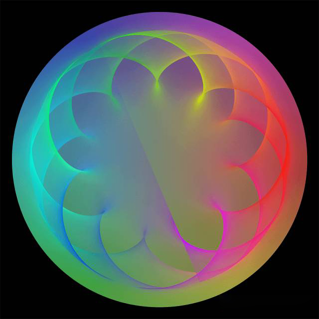
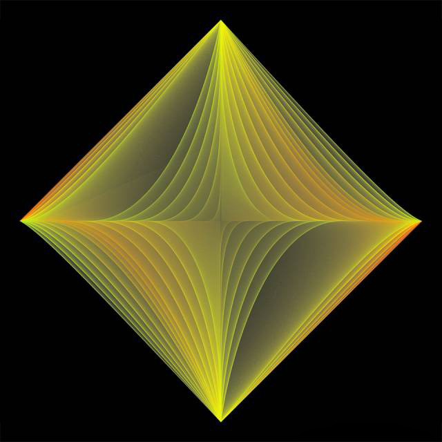
Adjust different speed and radius, the patterns formed will be different too. Try to change variables like angle, speed, radiusX, radiusY and see what will happen.
Layer Blending Mode
The various color modes we talked in the before are alll used to color graphics’components. Except to use this method to control color, Processing can use various layers’ blending modes like Photoshop. Open layer window in PS, click to choose layers’ blending mode, then we can see these options.
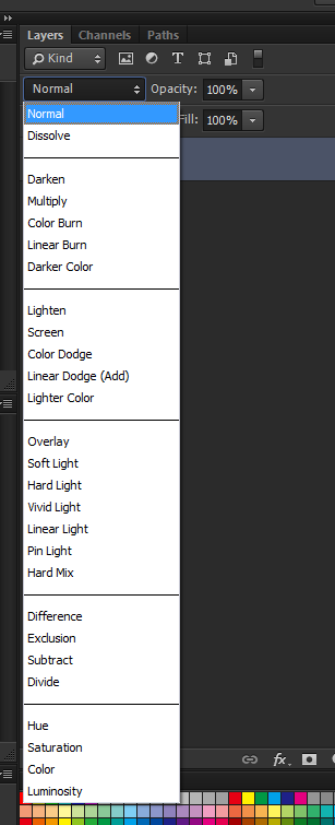
These are existed layer modes in PS. To speak it simply, blending mode can be regarded as a kind of color calculation mode. It will decide which color will be created in the last when “color A” plus “color B” . Here “ color A” means the color behind the current layer(also called base color). “ color B” means the color of the current layer(also called mixed color). The program will calculate to obtain color C according to the RGB value and alpha of color A and B. It will be displayed at the screen as a result color. Different layer mode stands for different calculation methods. In the next half part of this series of articles, we will go on explain it in details. Now we only have to know its usage first. Let’s look at an example of using Add Mode in program. Code Example(9-8):
[cceN_cpp theme=”dawn”] PImage image1,image2; void setup(){ size(800,400); image1 = loadImage(“1.jpg”); image2 = loadImage(“2.jpg”); } void draw(){ background(0); blendMode(ADD); image(image1,0,0,400,400); image(image2,mouseX,mouseY,400,400); } [/cceN_cpp]
Result:

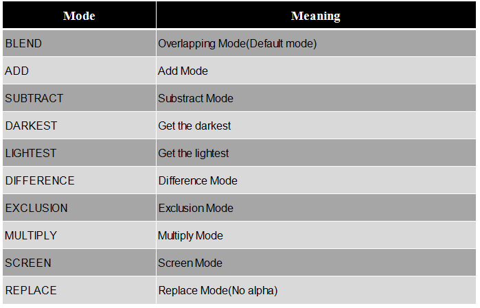
Function blendMode() is used to set graphics’ blending mode. We fill in ADD behind means we have set Add Mode. In program, there is no concept of layer. But because there is drawing sequence of the graphic components, thus when blending pictures, image 1 is regarded as base color and image 2 as mixed color. ADD mode belongs to “Brighten Class”. After using it, you will get a brightened effect. Below is a blending mode that can be used in Processing.
Processing Blending Mode
We can try to change different blending mode to see the effect. When example (9-8) has adopted overlapping mode (the background should be set to white) :
After using Substract Mode (the background should be set to white) :
Layer Blending Mode Application Case
Blending mode can not only be used to pictures, but also suitable for all graphic components in the canvas. Below has displayed an usage about Add Mode. It can be used to analog various lighting effects. Code Example(9-9):
[cceN_cpp theme=”dawn”] void setup() { size(400, 400); } void draw() { background(0); blendMode(ADD); int num = int(3000 * mouseX/400.0); for(int i = 0;i < num;i++){ if(random(1) < 0.5){ fill(0,50,0); }else{ fill(50); } ellipse(random(50,width – 50),random(50,height – 50),20,20); } } [/cceN_cpp]
Here, through function random, we have blended green color and white color,which have carried alpha already, into the particles. We can use mouse to control the quantity of circle and watch the overlapping effect. ADD and SCREEN are quite similar. Although it is same to brighten, there are subtle differences. You can replace it to SCREEN and make comparison. After being overlapped, the purity and brightness of ADD will be higher. It is suitable for analoging the lighting effect. As for color, here we has come to an end in this chapter. For this “language”, you have already mastered enough vacabularies. Now, hurry up to use code to enjoy the world of shape and color!
Relative Readings:
Interesting Programming Guidance for Designer——Processing Initial Touch Interesting Programming Guidance for Designer–Create Your First Processing Program Interesting Programming Guidance for Designer–Get Your Picture Running(Part One) Interesting Programming Guidance for Designer–Get Your Picture Running(Part Two) Interesting Programing Guidance for Designer–Program Process Control- Loop Statement Interesting Programming Guidance for Designer–Program Process Control–Condition Statement (Part One) Interesting Programming Guidance for Designer–Program Process Control–Condition Statement (Part Two) Interesting Programming Guidance for Designer–Custom Functions and Fractal Recursion Interesting Programming Guidance for Designer–Custom Functions and Fractal Recursion