ProtoBoard Revolution – Flower ProtoBoard
January 12, 2019
Freaduino Starter Kit
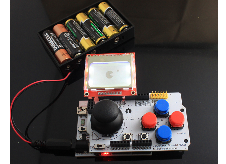
January 12, 2019Hi Guys, Joystick v2.0 is our new product which added Nokia 5110 LCD and nRF24L01 interface. You can easily develop your Joystick games, and even communicate with each other with wireless nRF24L01. I just made a simple demo game based on Joystick Game Kit, we called — Greedy Freak.
Take a look firstly: https://www.youtube.com/watch?v=wQuIPCIZxrA
If you want to write your own Joystick game, follow me and see what kind of preparation do you need?
Hareware
- Joystick v2.0
- Freaduino ATmage328
- Nokia 5110 LCD
- nRF24L01 (Non-essential)
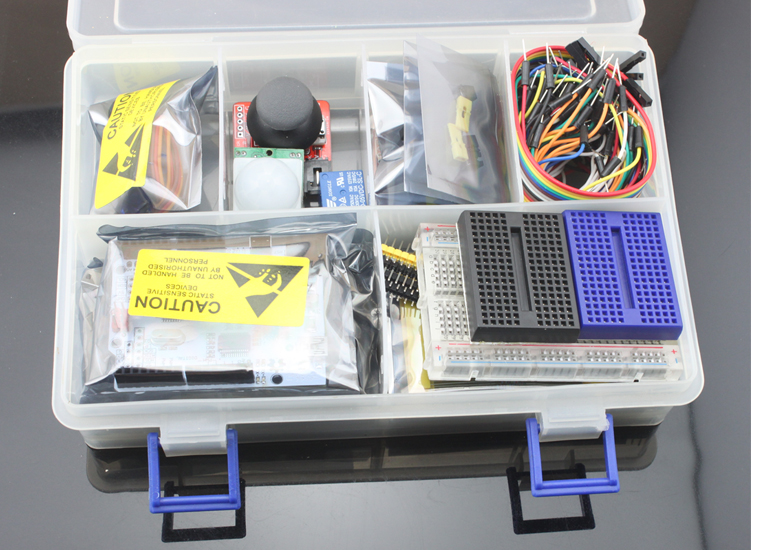
We have prepare Joystick Game Kit for starter now, there is no soldering required and you can start your project quickly. Another important reason choose the Joystick Game Kit is the Joystick v2.0 with Nokia5110 is not support standard Arduino board Because of standard Arduino board 3.3v just supply 50mA current, which can’t support Nokia5110 backlight need. But our Freaduino support 800mA current which far more than Nokia5110’s demand.
Software
Greedy Freak is base on a Nokia 5110 LCD library — LCD5110_Graph library written by our friend Henning Karlsen. Put the library to your \arduino-00xx\libraries\. The LCD 5110 pin define with Arduino as below:
SCLK – D9 , MOSI – D10 , D/C – D11 , RST – D12 , SCE – D13
[cce_cpp]LCD5110 myGLCD(9,10,11,12,13);[/cce_cpp]
The nRF24L01 pin define with Arduino as:
SCE – D9 , CSN – D10 , SCK – D13 , MOSI – D11 , MISO – D12
[cce_cpp]
#define CE       9
// CE_BIT:   Digital Input     Chip Enable Activates RX or TX mode
#define CSN      10
// CSN BIT:  Digital Input     SPI Chip Select
#define SCK      13
// SCK BIT:  Digital Input     SPI Clock
#define MOSI     11
// MOSI BIT: Digital Input     SPI Slave Data Input
#define MISO     12
// MISO BIT: Digital Output    SPI Slave Data Output, with tri-state option
[/cce_cpp]
Because of the data pin with Nokia 5110 and nRF24L01 is multiplexing, the demo game no support them at same time. Maybe we can design another Joystick Mage2560 for more IO in future. Now, Greedy Freak full code just as below, you can see it’s realy simple.
[cce_cpp]
/*********************************************************************
**  Device: Joystick  -- Greedy Freak v1.0                          **
**  File:   EF_Joystick_v2.0_Game.pde                               **
**								    **
**  Created by ElecFreaks Robi.W /25 Nov 2011                       **
**                                                                  **
**  Description:                                                    **
**  This file is a sample code for your reference.                  **
**                                                                  **
**  Copyright (C) 2011 ElecFreaks Corp.                     	    **
*********************************************************************/

#include <LCD5110_Graph.h>
#include <avr/pgmspace.h>

LCD5110 myGLCD(9,10,11,12,13);

extern uint8_t SmallFont[];

uint8_t pacman1[] PROGMEM={
0x80, 0xE0, 0xF0, 0xF8, 0xFC, 0xFE, 0xFE, 0xFF, 0xFF, 0xFF, 0xFF, 0xFF, 0xFF, 0x7E, 0x3E, 0x1C,   // 0x0010 (16) pixels
0x0C, 0x00, 0x00, 0x00, 0x1F, 0x7F, 0xFF, 0xFF, 0xFF, 0xFF, 0xFF, 0xFF, 0xFF, 0xFF, 0xFF, 0xF9,   // 0x0020 (32) pixels
0xF0, 0xE0, 0xC0, 0x80, 0x00, 0x00, 0x00, 0x00, 0x00, 0x00, 0x00, 0x01, 0x03, 0x07, 0x07, 0x0F,   // 0x0030 (48) pixels
0x0F, 0x0F, 0x0F, 0x0F, 0x0F, 0x07, 0x07, 0x03, 0x03, 0x00, 0x00, 0x00,
};

uint8_t pacman2[] PROGMEM={
0x80, 0xE0, 0xF0, 0xF8, 0xFC, 0xFE, 0xFE, 0xFF, 0xFF, 0xFF, 0xFF, 0xFF, 0xFF, 0xFE, 0xFE, 0x7C,   // 0x0010 (16) pixels
0x7C, 0x38, 0x20, 0x00, 0x1F, 0x7F, 0xFF, 0xFF, 0xFF, 0xFF, 0xFF, 0xFF, 0xFF, 0xFF, 0xFF, 0xF9,   // 0x0020 (32) pixels
0xF9, 0xF0, 0xF0, 0xE0, 0xE0, 0xC0, 0x40, 0x00, 0x00, 0x00, 0x00, 0x01, 0x03, 0x07, 0x07, 0x0F,   // 0x0030 (48) pixels
0x0F, 0x0F, 0x0F, 0x0F, 0x0F, 0x07, 0x07, 0x03, 0x03, 0x01, 0x00, 0x00,
};

uint8_t pacman3[] PROGMEM={
0x80, 0xE0, 0xF0, 0xF8, 0xFC, 0xFE, 0xFE, 0xFF, 0xFF, 0xFF, 0xFF, 0xFF, 0xFF, 0xFE, 0xFE, 0xFC,   // 0x0010 (16) pixels
0xF8, 0xF0, 0xE0, 0x80, 0x1F, 0x7F, 0xFF, 0xFF, 0xFF, 0xFF, 0xFF, 0xFF, 0xFF, 0xFF, 0xFF, 0xFF,   // 0x0020 (32) pixels
0xFF, 0xFF, 0xFF, 0xFF, 0xFB, 0xF9, 0x79, 0x19, 0x00, 0x00, 0x00, 0x01, 0x03, 0x07, 0x07, 0x0F,   // 0x0030 (48) pixels
0x0F, 0x0F, 0x0F, 0x0F, 0x0F, 0x07, 0x07, 0x03, 0x01, 0x00, 0x00, 0x00,
};

uint8_t pill[] PROGMEM={
0x0E, 0x1F, 0x1F, 0x1F, 0x0E,
};
#define Width  84
#define Hight  48
#define Range  12

int FirstShotX , FirstShotY;
int PointX, PointY;
int delaytime;

void setup()
{
  /* Init LCD5110_Graph library */
  myGLCD.InitLCD();
  myGLCD.setFont(SmallFont);
  randomSeed(analogRead(0));

  /* Record Joystick corrected coordinates */
  FirstShotX = analogRead(A0);
  FirstShotY = analogRead(A1);

  /* Black specks the initial coordinates */
  PointX = 75;
  PointY = 20;

  /* Refresh time */
  delaytime = 50;

  /* Start display */
  myGLCD.print("ElecFreaks", CENTER, 0);
  myGLCD.print("Joystick v2.0", CENTER, 20);
  myGLCD.print("Greedy Freak", CENTER, 40);
  myGLCD.update();
  delay(3000);

  /* Init Serial port */
  Serial.begin(115200);
}

void loop()
{
  //int pacy=random(0, 42);
  uint8_t* bm;

  for (int i=-20; i<84; i++)
  {
    /* Clear LCD */
    myGLCD.clrScr();

    /* Refresh Greedy Freak Bitmap */
    switch(((i+20)/3) % 4)
    {
      case 0: bm=pacman1;
              break;
      case 1: bm=pacman2;
              break;
      case 2: bm=pacman3;
              break;
      case 3: bm=pacman2;
              break;
    }
    int sensorValueX = (analogRead(A0) - FirstShotX)*0.1 + 32;        //You can change the coefficient such as 0.08, which decide X-axis Range
    int sensorValueY = (FirstShotY - analogRead(A1))*0.06 + 14;        //You can change the coefficient such as 0.04, which decide Y-axis Range

    myGLCD.drawBitmap(sensorValueX, sensorValueY, bm, 20, 20);
    /* Once the Greedy Freak be close to black specks, random another X and Y */
TX:
    if( (sensorValueX-5 <= PointX && PointX <= sensorValueX+15) && (sensorValueY-3<= PointY && PointY <= sensorValueY + 20 ))
    {
       PointX = random(0, 80);
       PointY = random(0, 43);
       goto TX;
    }
    else
      myGLCD.drawBitmap(PointX, PointY, pill, 5, 5);

    myGLCD.update();        //update and display the Bitmap

    int i, someInt, flag = 0;
    for(i=2; i<9; i++)
    {
      someInt = digitalRead(i);        //scan the KEY
      if(someInt == 0)
      {
        flag =1;
        break;
      }
     }
     if(flag == 1)
     {
       Serial.println(i);
       switch(i)
       {
         case 2: Serial.println("--------> Button A");
                 delaytime = 50;
                 break;
         case 3: Serial.println("--------> Button B");
                 delaytime = 5;
                 break;
         default: break;
       }
       flag=0;
     }
    delay(delaytime);
  }
}

[/cce_cpp]
Download


