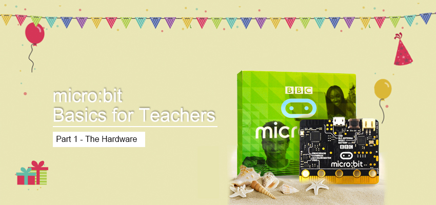
Are you a teacher who wants to use micro:bit in your classroom, but doesn’t know where to start? We’ll show you how!
1 x BBC micro:bit board Or 1 x micro:bit Board with Battery Holder kit
At Hackster we know that learning new technologies and tools for use in the classroom can be time consuming and daunting for many teachers. To help with this, we have partnered with the Micro:bit Foundation to create three short, informative video lessons that will give you the confidence to use the micro:bit in your classroom, without wasting time with extraneous details. Watch the video version here: https://youtu.be/RkWDYTx_mg4
A micro:bit is a tiny programmable computer, designed to make learning and teaching easy and fun. Studieshave found that using physical computing devices, like the micro:bit, in the classroom increases motivation, collaboration, creativity, and results in concrete understanding of programming concepts. In addition, the micro:bit can be used to teach concepts in many subject areas including math, science, engineering, and even arts!
When you receive your micro:bit, it will come in a box like this: 
You will find a getting started guide and important safety instructions. Under the guides there is a small bag that contains the micro:bit. If you lift up the white cardboard in the box you will find a battery case, two AAA batteries, and the USB connector to connect the micro:bit to your PC. When you are using your micro:bit you can power it with your computer using the USB cable, or with the battery pack containing two AAA batteries. 


 When you connect your micro:bit to your computer you’ll notice that your micro:bit lights up. This is the beginning of the demo display. Your micro:bit will prompt you to press button A, followed by button B then you’ll see the word “SHAKE!” scroll across the screen. If you shake your micro:bit, you will see a light display. The final part of the demo will ask you to “CHASE” which means you will try to move the steady light dot to the same place as the flashing dot by tilting the micro:bit.
We will delve into two options for coding with your microbit in our next videos, but first let’s go over the parts of the micro:bit and how they work.
The most distinct part of the micro:bit is the light display, which is on the front of the micro:bit.  This display is made of up a 5×5 grid of LEDs. LED is short for ‘light emitting diode’. They were invented in the 60s, and since then have become popular as a low power lightbulb and have replaced halogen and flourescent bulbs in most homes and buildings. The 25 sparkly lights on the front of your microbit are LEDs. They can be programmed to display various words and designs. You can also program the display to turn off or dim the brightness of the LEDs.
  There is also a yellow light on the back of your micro:bit. This light will flash to indicate that something has changed like when you upload a new code to the micro:bit, that means the code has been successfully updated.
On either side of the LED grid display on the front of your micro:bit you will see a button. These buttons are labeled A and B and are used as input for the micro:bit. The micro:bit can detect which button is pressed and react to the button press or send information to another device depending on how you have programmed your micro:bit. 
 The button on the back of the micro:bit next to the USB connector is the reset button. Use this button to start your code from the beginning, or to run new code after you have uploaded it to your device.
The micro:bit has a built in compass that can be used to measure the magnetic fields around the micro:bit and determine the direction the micro:bit is facing. This information can be used in many different ways including turning the micro:bit into a compass, or to send directional information to another device. 
The micro:bit has a built in accelerometer, which is used for detecting specific motions and the speed of the micro:bit.  Using the accelerometer, the micro:bit can detect when someone shakes, tilts, or drops the device. There are endless ways you can use this feature in your programs such as creating a pedometer that measures each step taken or measuring the acceleration of an object by attaching the micro:bit and sliding it down a ramp, or even just measuring movement like a shake of the micro:bit to simulate the roll a die like this example. Each time you shake the micro:bit the accelerometer detects the movement and displays a random number from 1-6.


On the bottom of the micro:bit you will notice a “ruler” looking feature with holes and labels.  There are a total of 25 pins which are separated into small pins and large pins. You will mostly be using the large pins which are the pins with holes labeled 0, 1, 2, 3V, and GND which stands for ground. Pins 0, 1, and 2 are general purpose input and output pins – abbreviated GPIO. These pins can be used for both input and output and can be connected to various devices such as thermometers or speakers using alligator clips or 4mm banana plugs. When connecting your devices using alligator clips, be sure to grip the board between the jaws of the clip without overlapping any of the smaller pins. If you overlap with the smaller pins this may prevent your code from working properly.

 The Pins Labeled 3V (three volts) and GND (ground) are the power supply pins. Make sure you never directly connect these pins together. The 3V pin allows you to power another device, or, if your micro:bit is not already being powered by your computer through the USB cable or external batteries, receive power from another device. Ground is used to complete the circuit if you are using your 3V to power another device. The small pins are the unlabeled segments between the large pins on your micro:bit. These pins are beyond the scope of this video, but if you want to learn more, please visit http://microbit.org/guide/hardware/pins/to see a labeled diagram and learn the function of each pin.
On the back of your micro:bit you can see the labeled “BLE Antenna” which stands for “Bluetooth Low Energy Antenna”. This antenna allows the micro:bit to communicate with other devices, such as your phone or tablet, wirelessly by sending and receiving signals to and from that device: 
The micro:bit also has the capability to detect temperature. While it does not have its own temperature sensor. The microprocessor chip, which can be found on the back of the board – The brains of our computer – can detect changes in temperature. This means that while the temperature is not necessarily accurate at determining the actual temperature and may be off by a few degrees, it is precise and great at measuring the change in temperature.  Now that you have learned the basic features of the micro:bit, you can move on to lesson 2 where we will teach you how to program the micro:bit using Javascript. If you are not planning on using Javascript and will be using python instead, you can go straight to lesson 3. This article written by Katie Kristoff comes from hackster.io.