First of all, if you have any problem, please contact us any feedback is welcome, and the code does not use Arduino’s SPI library, but the software imitates SPI, maybe you can modify and complete it. The Arduino nRF24L01 module can be controlled in many ways, one of which is Arduino. We tried and tested it, then made a demo. Let’s see how it works with Arduino. First of all, of course, you need two Arduino boards and at least two RF modules(nRF24L01 pins, Arduino nRF24L01) one to transmit and the other to receive(nRF24L01 pins). If you don’t have them, you can get them in our store at a very low price. (Order nRF24L01 pins module) If you use a standard Arduino board, you should use the Arduino board’s 3.3V pin(VDD3V3???to provide power. Because the Arduino nRF24L01 module is worked at a 1.9-3.6V voltage level. Please note, do not use a 5V pin(VDD5V) to provide power, which may destroy it. The Demo pins to Arduino as below: GND – GND, VCC – 3.3V, CS – D8, CSN – D9, SCK – D10, MOSI – D11, MISO – D12, IRQ – D13 Download the code below into the TX Arduino (transmit) — This code will drive the Arduino nRF24L01module to send out data form 0×00 to 0xFF. Note, between the write TX_FIFO and clear RX_DR or TX_DS or MAX_RT interrupt flag, would be better not to serial print anything, which may be the case ACK failed.
[cce_cpp]
void setup()
{
SPI_DIR = ( CE + SCK + CSN + MOSI);
SPI_DIR &=~ ( IRQ + MISO);
// attachInterrupt(1, _ISR, LOW);// interrupt enable
Serial.begin(9600);
init_io(); // Initialize IO port
unsigned char status=SPI_Read(STATUS);
Serial.print("status = ");
Serial.println(status,HEX); // read the mode’s status register, the default value should be ‘E’
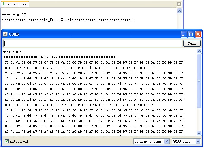
Serial.println("*******************TX_Mode Start****************************");
TX_Mode(); // set TX mode
}
void loop()
{
int k = 0;
for(;;)
{
for(int i=0; i<32; i++)
tx_buf[i] = k++;
unsigned char status = SPI_Read(STATUS); // read register STATUS's value
if(status&TX_DS) // if receive data ready (TX_DS) interrupt
{
SPI_RW_Reg(FLUSH_TX,0);
SPI_Write_Buf(WR_TX_PLOAD,tx_buf,TX_PLOAD_WIDTH); // write playload to TX_FIFO
}
if(status&MAX_RT) // this is retransmit than SETUP_RETR
{
SPI_RW_Reg(FLUSH_TX,0);
SPI_Write_Buf(WR_TX_PLOAD,tx_buf,TX_PLOAD_WIDTH); // disable standy-mode
}
SPI_RW_Reg(WRITE_REG+STATUS,status); // clear RX_DR or TX_DS or MAX_RT interrupt flag
delay(1000);
}
}
[/cce_cpp]
Download the code below into the RX nRF module (receive) – This code will drive the Arduino nFR24L01module to receive the data that transmit from the TX nRF module and print it to the serial port. Note, clear RX_FIFO must bellow Read_FIFO
[cce_cpp]
void setup()
{
  SPI_DIR = ( CE + SCK + CSN + MOSI);
  SPI_DIR &=~ ( IRQ + MISO);
  //  attachInterrupt(1, _ISR, LOW); // interrupt enable
  Serial.begin(9600);
  init_io();                        // Initialize IO port
  unsigned char status=SPI_Read(STATUS);
  Serial.print("status = ");
  Serial.println(status,HEX);      // read the mode’s status register, the default value should be ‘E’
  Serial.println("*****************RX_Mode start******************************R");
  RX_Mode();                        // set RX mode
}
void loop()
{
  for(;;)
  {
    unsigned char status = SPI_Read(STATUS);                // read register STATUS's value
    if(status&RX_DR)                                        // if receive data ready (TX_DS) interrupt
    {
      SPI_Read_Buf(RD_RX_PLOAD, rx_buf, TX_PLOAD_WIDTH);    // read playload to rx_buf
      SPI_RW_Reg(FLUSH_RX,0);                               // clear RX_FIFO
      for(int i=0; i<32; i++)
      {
          Serial.print(" ");
          Serial.print(rx_buf[i],HEX);                      // print rx_buf
      }
      Serial.println(" ");
    }
    SPI_RW_Reg(WRITE_REG+STATUS,status);                    // clear RX_DR/TX_DS/MAX_RT interrupt flag
    delay(1000);
  }
}
[/cce_cpp]
Now power on both nrf modules, and connect the RX one to the PC via USB. Open the IDE serial port monitor, change the baud rate to 9600 bps, and you can see the data that was received from the nRF24L01 pins. If you want to change the nRF24L01 pins connecting to the nRF module, just modify the definition on the Arduino NRF24L01. h. All the projects here(including API.h and Arduino NRF24L01.h)

Download nRF24L01_Demo_For_Arduino. Download nRF24L01_Demo_For_Arduino_v1.1. nRF24L01 with Arduinio’s SPI Library