Often, without our eyes and ears, our hands and feet are not as accurate as they could be, because we get feedback through our eyes and ears. Our brain can use the feedback to constantly correct the movement of our hands and feet, creating closed-loop feedback. If we need to use PWM to precisely control the brightness of an LED, we need feedback, but the brightness of the LED is an analogue signal.
Our MCU is not able to process the analogue signal directly, it needs to be converted into a digital signal before it can be processed, so how can we convert the analogue signal into a digital signal? This is where Pico:ed’s ADC function shines through.
Introduction
The analogue-to-digital converter (ADC) is a converter that converts an analogue signal with continuous time and continuous amplitude into a digital signal with discrete time and discrete amplitude. The corresponding binary values converge one after another until the input voltage agrees with the internal comparison voltage, and then the binary value representing that voltage is output.
In short, a value is obtained and compared to a set value, and the closest value is obtained by continuous comparison.
SAR
A series of voltages are generated from the reference voltage and compared with the input voltage one by one to obtain the code corresponding to the closest input voltage.
Parallel Comparator type ADC
A series of voltages are generated from the reference voltage and compared simultaneously to obtain the corresponding coded value closest to the input voltage, which is characterised by high speed and low accuracy and is suitable for high-speed and low-resolution applications.
The difference between the two types
The difference between successive approximation ADCs and parallel comparison ADCs is similar to that between a CPU and a GPU.
The former can process more difficult events individually, while the latter processes simpler events in parallel.
ADC type: Successive approximation ADC (SAR ADC).
Conversion rate: 500kS/s (using internal independent 48M clock).
Resolution:12bit.
ADC input channels: Channels 0-3 are GPIO channels (GPIO26-29), Channel 4 is the internal temperature sensor channel.
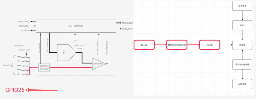
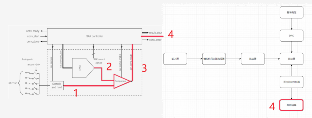
This diagram is the official ADC block diagram.
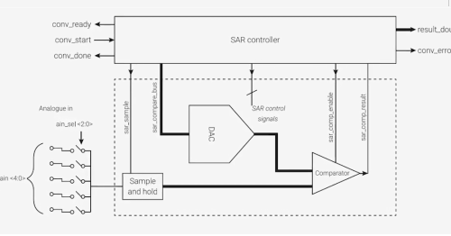
From the above diagram, the ADC flow can be summarised as shown in the diagram.
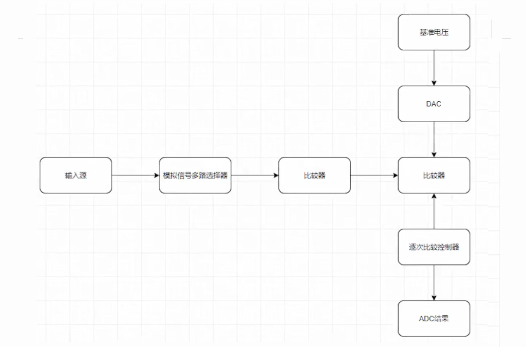
The analog signal goes to one end of the comparator via the analog signal multiplexer.
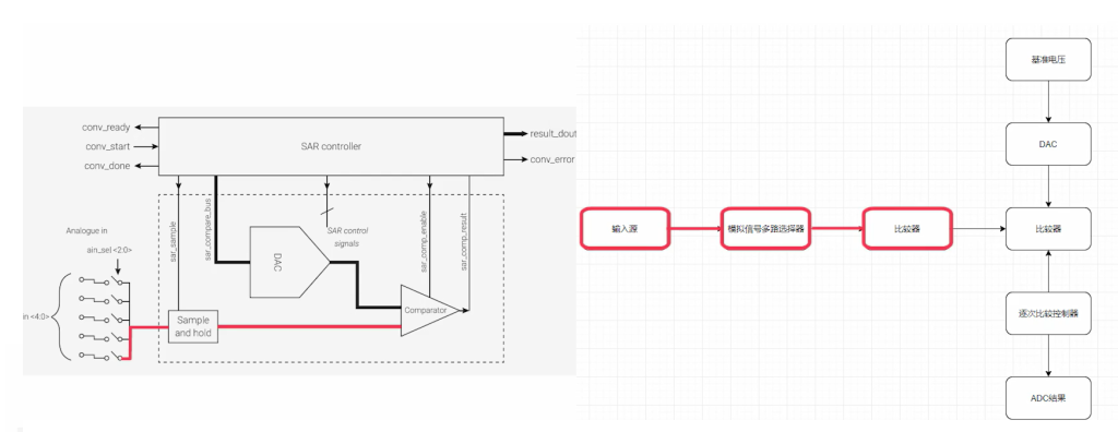
If we need to capture the voltage of ADC channel 0, i.e. the voltage on the GPI026 pin, it will go to one end of the comparator via the analogue signal multiplexer.
A DAC is a flat division of the reference voltage (which can be considered the maximum voltage measured) into N parts of 2.

If we have a resolution of 12 bit the reference voltage is divided equally into 4096 parts of its output.
1. After the successive comparison controller is ready, it starts to work when the start conversion signal arrives and outputs the successive comparison control signals (SAR control signals)
2. The control comparator compares the input voltage with the generated internal voltage on a step-by-step basis
3. The successive comparison controller will record the result of the comparison
4. The ADC conversion is completed by outputting the closest binary value to the input voltage after the comparison has been completed.
The generic ADC input voltage calculation formula is as follows.
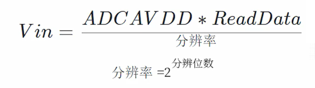
Multiplying the reference voltage by the ADC reading and dividing by the resolution equals the input voltage of the ADC input pin and substituting the parameters in Pico, we can simply deduce the ADC input voltage calculation formula as follows.
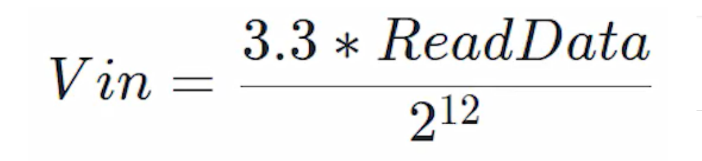
3.3 multiplied by the ADC reading divided by 4096 equals the ADC pin input voltage in V (Volts).
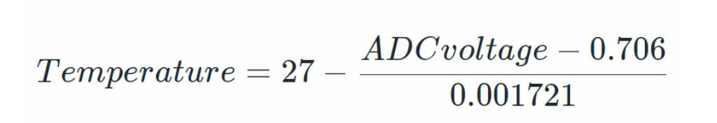
Because it is the production of thermometers, you need to understand the official formula for calculating the on-chip temperature sensor.
The formula is as follows, substituting the ADC reading voltage value to get the current temperature.
The logic of the code is written according to ADC conversion theory, starting with the content of the functions used.
machine.ADC(id) function
The parameter ID is the ADC channel to be used, you can use the Pin object or specify the ADC channel directly.
When using the Pin object, the specified GPIO must support the ADC function, i.e. GPIO26-29.
When using the specified ADC channel, channels 0-3 correspond to GPI026-29 and channel number 4 corresponds to the temperature sensor on the chip.
ADC.read_u16() function
Its role is to read the corresponding channel ADC, and return to read the value, here we need to pay attention to one point, the function returns the value is not directly returned to the ADC read value but after processing the value, the value range is 0-65535.
Therefore, the ADC voltage calculation formula should be
ADC ReadData is 3.3 multiplied by the return value divided by 65535 in V
6. REALIZATION STAGE
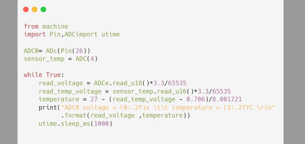
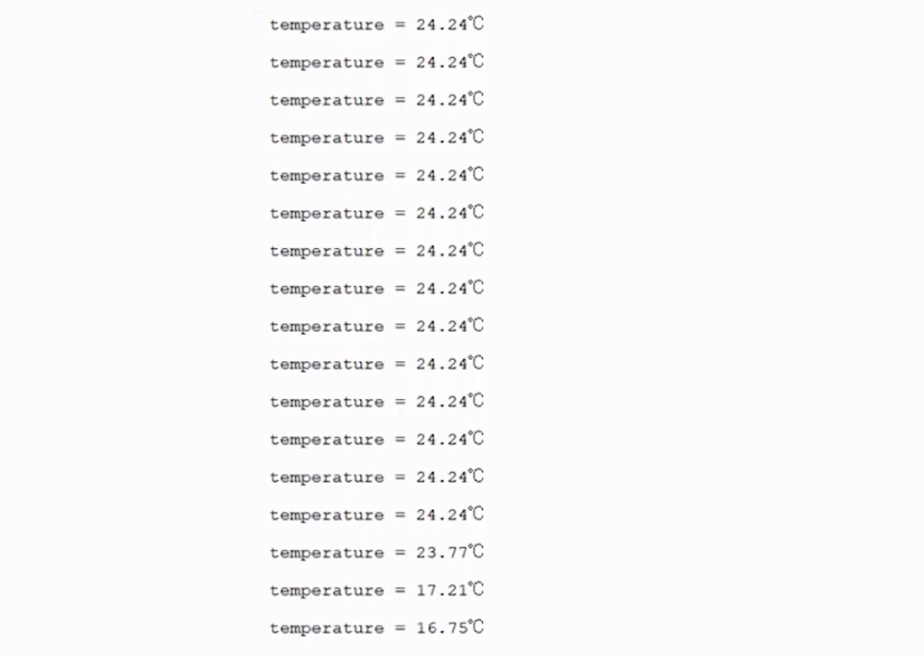
This program reads the voltage on GPIO26 once per second and collects the temperature using the on-chip temperature sensor.
In the first few lines of the program, you need to import the corresponding function library.

Here we use two ways to initialize the ADC channels, specifying that ADC channel 4, which corresponds to the on-chip temperature sensor, is initialized. Then we see the while dead loop, which reads the voltage on ADC channel 4 and then substitutes it into the official temperature calculation formula:
The current temperature is calculated and output to the console. Open the thorny and click on the Run button and you will see that the Pico outputs the current temperature every second.
Now we can see the change in temperature by touching a colder object on the tablet.