


nRF24L01 with Arduinio’s SPI Library
January 4, 2019The Easy Radio A7125 Reference Code Generator
January 4, 2019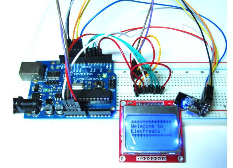
We just get the easy radio RF A7125 module, which is a high performance and low cost 2.4GHz ISM band wireless transceiver. The A7125 module can be controlled in many ways, one of which is Arduino. We tried and tested it, then made a demo. Let’s see how it works with Arduino, and how to implement two-way radio and how to initial A7125. First of all, of course, you also need two Arduino boards and at least two RF modules, one to transmit and the other to receive, every A7125 can be defined to Master(TX) or Slave(RX). If you don’t have, you can get them in our store in a very low cost. (Order A7125 module) You should use the Arduino board’s 3.3V pin(VDD3V3???to provide power. Beacuse the A7125 module is worked at 1.9-3.6V voltage level. Please note, do not use 5V pin(VDD5V) to provide power. I have made a mistake used 5V to provide power, luckly its OK, I think you’d better not try again 🙂 We made two demo for A7125 , software SPI mode and hardware SPI mode. software SPI mode through software simulation SPI and hardware SPI mode used Arduinos board’s SPI interface and library. You can download the full code at post end. The Hardware SPI Mode Demo pins to Arduino as below you should comply with Arduinos SPI interface definition: GND – GND, VCC – 3.3V, SCS – D8, CSN – D9, GPIO1 – D10, SDIO – D11, GPIO2 – D12, SCK – D13 The Software SPI Mode Demo pins to Arduino as below: GND – GND, VCC – 3.3V, SCS – D8, CSN – D9, SCK – D10, SDIO – D11, GPIO1 – D12, GPIO2 – D13 There we used software SPI mode definition for tested. A7125 Module has two working mode: Direct Mode and FIFO Mode. which are be controled by Mode Control Register(0x01h), bit FMS([0] Direct mode, [1] FIFO mode), at there we used FIFO mode for tested.
The code must include “A7125reg.h” that includes all registers and command definition. At Master side: After power on and initial RF chip procedure, Master will deliver 64 bytes data TX FIFO, the jump into RX state to wait ACK data from Slave. If Master receives the ACK data, it will back to TX state to deliver next 64 byte data. If Master dose NOT receive the ACK data, Master will also back to TX state for next 64 byte data delivery after staying in RX state for 50 ms.

Download the code below into the TX Arduino (transmit) — This code will drive the A7125 module to send out buffer data.
[cce_cpp]
const Uint8 PN9_Tab[]={ '*','*','*','*','*','*','*','*','*','*','*','*','*','*',
                        'W','e','l','e','c','o','m','e',' ','t','o',' ',' ',' ',
                        'E','l','e','c','F','r','e','a','k','s',' ','!',' ',' ',
                         '*','*','*','*','*','*','*','*','*','*','*','*','*','*'};
[/cce_cpp]
[cce_cpp]
void setup()
{
    Serial.begin(9600);
    delay(50);
    //init io pin
    SPI_DIR  = ( SCS + SCK + SDIO);
    SPI_DIR &=~(GIO1 + GIO2 );
    SPI_PORT = (SCS+SDIO) ;
    SPI_PORT &=~SCK;

    Serial.println("------------>send start here.");
    initRF();
    StrobeCmd(CMD_STBY);
    A7125_WriteReg( TXTEST_REG, 0x17 );     //  TX power = 0dBm
    A7125_WriteReg( DATARATE_REG, 0x1F );   //  Data rate = 2M
    A7125_WriteReg( MODECTRL_REG, 0x62 );   //  FIFO mode
    A7125_WriteReg( PLL1_REG, 100 );        // set radio channel
    A7125_WriteReg( CODE1_REG, 0x0F);       //  enable CRC check function
    WriteFIFO( 64 );
    delay(50);
}

void loop()
{
      StrobeCmd( CMD_TX );	            //send data mode

      while(SPI_IN & RF_WTR);              // wait RFIC receive data

      StrobeCmd( CMD_SLEEP ); // let RF to sleep mode
      delay(10);
      StrobeCmd(CMD_STBY); //entry standby

      Serial.println("------------>Send complate!");
      delay(1000);
}
[/cce_cpp]
Slave side: After power on and initial RF procedure. Slave enters into RX state for receiving data from Master. Slave is set to stay in RX state until it receives teh data. If Slave receives the data from Master, it will transit to TX state to deliver 64 bytes ACK data and the back to RX state for receiving next 64 byte data from Master.

Download the code below into the RX Arduino (receive) – This code will drive the A7125 module to receive the data that transmit form the TX module and print it to serial port and Nokia 5110 LCM display, and you should impore EF5110 library.
[cce_cpp]
EF_LCM5110  lcm(3,4,5,6,7);
void setup()
{
    Serial.begin(9600);
    delay(50);
    //init io pin
    SPI_DIR  = ( SCS + SCK + SDIO);
    SPI_DIR &=~(GIO1 + GIO2 );
    SPI_PORT = (SCS+SDIO) ;
    SPI_PORT &=~SCK;

    Serial.print("------------>start here.");
    initRF();
    A7125_WriteReg( TXTEST_REG, 0x17 );         //  TX power = 0dBm
    A7125_WriteReg( DATARATE_REG, 0x1F );       //  Data rate = 2M
    A7125_WriteReg( MODECTRL_REG, 0x62 );       //  FIFO mode
    A7125_WriteReg( PLL1_REG,100);              // set radio channel
    A7125_WriteReg( CODE1_REG, 0x0F);           //  enable CRC check function
    A7125_WriteReg( FIFO1_REG, 10-1 );           // set FIFO length
    delay(50);
    lcm.init();
    lcm.clearLCM();
}

void loop()
{
      StrobeCmd(CMD_RX);		       //accept data mode

      TmpUint8 = A7125_ReadReg(MODE_REG);
      while(SPI_IN & RF_WTR);                  // wait RFIC receive data

      if((TmpUint8&0x20)==0)
      {
               ReadFIFO(10);	              // CRC pass, read RX FIFO
               for(int i=0; i< 10; i++)
               {
                  //lcm.write_char(RfBuf[i]-32);
                  lcm.write_string(0,i,(char*)RfBuf);
                  Serial.print(";buf=");
                  Serial.print(RfBuf[i], HEX);
                }
                Serial.println();
                delay(50);
      }
      StrobeCmd(CMD_STBY); //entry standby
      delay(1000);
}
[/cce_cpp]
Now power on both Arduino , and connect the RX one to PC via USB. Open the IDE serial port monitor , change the baud rate to 9600 bps , and you can see the data that received and same time you can see 5110 display as below. If you want to change Arduino pin connecting to module , just modify the define on the define.h OK, the next thing is do youself and make a your easy radio.

Download the demo for Arduino software SPI. Download the demo for Arduino hardware SPI. Download the library of Nokia 5110 for Arduino.