


LC meter – LC100x User Guide
January 4, 2019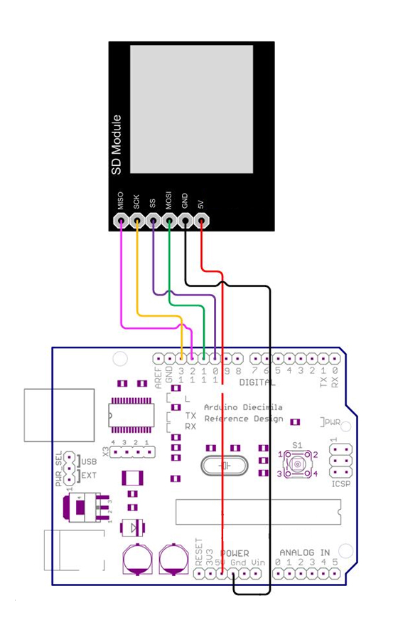
SD&MMC Card Module
January 4, 2019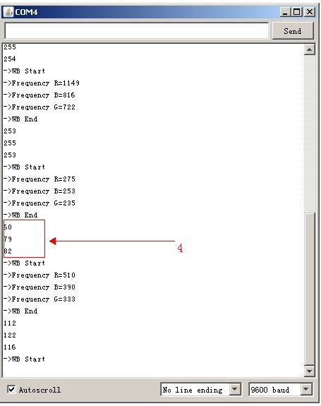
The TSC230/3200 is Programmable Color Light-to-Frequency Converter Module, which we have in stock about a week. It can be controlled in many ways, one of which is Arduino. We tried and tested it, then made a demo. Let’s see how it works with Arduino. First of all, of course material preparation. The ChipKit which you need one of Arduino main board and some of F/F jumper wire(3 pin & 4 pin &5 pin) andTSC230 Color Snsor Module. From now on, we provide two types of the TSC230 module with different layout. Here we use the white Color Sensor Module for the demo. The module works at 5V, you can use Arduino for power supply directly. The White Color Sensor has shorted LED to GND by a short circuit Block Cap. The four white highlight LEDs in the surrounding are providing a source constant light. The Demo pins to Arduino as below: GND & LED – GND , OE – GND, VCC – VCC, S0 – D6, S1 – D5, S2 – D4, S3 – D3, OUT – D2
[cce_cpp]
#define S0     6
#define S1     5
#define S2     4
#define S3     3
#define OUT    2
[/cce_cpp]
Here OE connects to GND that means the module was always enable. The OUT(Signal pin) is output of a square wave (50% duty cycle) with frequency directly proportional to light intensity (irradiance). Most Arduino boards have two external interrupts: numbers 0 (on digital pin 2) and 1 (on digital pin 3). So we connect OUT to D2 for counting the square wave frequency using external interrupt 0. So you need an other timer library which is a collection of routines for configuring the 16 bit hardware timer called Timer1 on the ATmega168/328 . Get the Timer1 Library. The initialization function of the demo as below:
[cce_cpp]
// Init TSC230 and setting Frequency.
void TSC_Init()
{
  pinMode(S0, OUTPUT);
  pinMode(S1, OUTPUT);
  pinMode(S2, OUTPUT);
  pinMode(S3, OUTPUT);
  pinMode(OUT, INPUT);

  digitalWrite(S0, LOW);  // OUTPUT FREQUENCY SCALING 2%
  digitalWrite(S1, HIGH);
}
[/cce_cpp]
The S0, S1 is output frequency scaling selection inputs. S0 – L & S1 – H is output frequency scaling to 2%. The reason of setting the scale factor is adapt to the different measurement range and improve the measurement ability with different MCU. The S2, S3 control the filter of RGB. Then is the important part of the demo code – Adjust the WB(white balance) .
[cce_cpp]
// Select the filter color
void TSC_FilterColor(int Level01, int Level02)
{
  if(Level01 != 0)
    Level01 = HIGH;

  if(Level02 != 0)
    Level02 = HIGH;

  digitalWrite(S2, Level01);
  digitalWrite(S3, Level02);
}

void TSC_Count()
{
  g_count ++ ;
}

void TSC_Callback()
{
  switch(g_flag)
  {
    case 0:
         Serial.println("->WB Start");
         TSC_WB(LOW, LOW);              //Filter without Red
         break;
    case 1:
         Serial.print("->Frequency R=");
         Serial.println(g_count);
         g_array[0] = g_count;
         TSC_WB(HIGH, HIGH);            //Filter without Green
         break;
    case 2:
         Serial.print("->Frequency B=");
         Serial.println(g_count);
         g_array[1] = g_count;
         TSC_WB(LOW, HIGH);             //Filter without Blue
         break;

    case 3:
         Serial.print("->Frequency G=");
         Serial.println(g_count);
         Serial.println("->WB End");
         g_array[2] = g_count;
         TSC_WB(HIGH, LOW);             //Clear(no filter)
         break;
   default:
         g_count = 0;
         break;
  }
}

void TSC_WB(int Level0, int Level1)      //White Balance
{
  g_count = 0;
  g_flag ++;
  TSC_FilterColor(Level0, Level1);
  Timer1.setPeriod(1000000);             // set 1s period
}

void setup()
{
  TSC_Init();
  Serial.begin(9600);
  Timer1.initialize();             // defaulte is 1s
  Timer1.attachInterrupt(TSC_Callback);
  attachInterrupt(0, TSC_Count, RISING);

  delay(4000);

  for(int i=0; i<3; i++)
    Serial.println(g_array[i]);

  g_SF[0] = 255.0/ g_array[0];     //R Scale factor
  g_SF[1] = 255.0/ g_array[1] ;    //G Scale factor
  g_SF[2] = 255.0/ g_array[2] ;    //B Scale factor

  Serial.println(g_SF[0]);
  Serial.println(g_SF[1]);
  Serial.println(g_SF[2]);

}
[/cce_cpp]
WB is to tell the system what is white. In theory, composed of equal amounts of RGB is white, but in fact RGB component values are not equal. For TSC230 module the sensitivity of the three light is different, which leading to RGB value different. So before you use it must be adjusted WB. The method of adjust the WB is in a fixed time(here used 1S) statistics RGB component’s pulses, then calculate a scale factor, this scale factor can be transformed the pulses count to 255. In the actual test, we calculate the number of pulses at same fixed time and multiply by the scaling factor and then get the object’s RGB values. Here we use the Timer1 library to set a callback function – void TSC_Callback() , for getting the RGB value. Pin D2(OUT) count the trigger when the pin goes from low to high: attachInterrupt(0, TSC_Count, RISING); At last, save the RGB value to g_array[] and calculate out the scale factor save to g_SF[].
Note: The first use or restart or change light and so on, please adjust the WB(White Balance) again. OK, Now we can test the light color from the demo code and print out the RGB value.
[cce_cpp]
void loop()
{
   g_flag = 0;
   for(int i=0; i<3; i++)
    Serial.println(int(g_array[i] * g_SF[i]));
   delay(4000);

}
[/cce_cpp]
First, after we have did all of previous. The result of the monitor as below:

As the figure, the
mark 1 is the RGB value at 1S period. The RGB value is Red=1126 , Green=707 and Blue =774. Then the
mark 2 is the scale factor. Then use the scale factor for adjusting the RGB value to 255 as
Mark 3. Then we measure objects in color, keep the objects on the module top 3s and the result from monitor as below:

As the figure, the
Mark 4 is object’s RGB value. Now you have got the RGB value it means you have got the object color. Left is your own personal test and enjoy it. This file is a sample code for your reference.Just a demo for TSC230 Programmable Color Light-to-Frequency Converter Module.
Thank you very much. Download the TCS230 Demo for Arduino