nRF24L01 Module Demo for Arduino

First of all, if you have any problem, please feel free to let us kown, and the code do not use Arduino’s SPI library, but softwore imitate SPI, maybe you can modified and complete it.

The nRF24L01 module can be controlled in many ways, one of which is Arduino. We tried and tested it, then made a demo. Let’s see how it works with Arduino.

First of all, of course, you need two Arduino boards and at least two RF modules, one to transmit and the other to receive. If you don’t have, you can get them in our store in a very low cost. (Order nRF24L01 module)

If you use a standard Arduino board, you should use the Arduino board’s 3.3V pin(VDD3V3) to provide power.  Beacuse the nRF24L01 module is worked at 1.9-3.6V voltage level. Please note, do not use 5V pin(VDD5V) to provide power, which may destroy it.

The Demo pins to Arduino as below:

GND – GND, VCC – 3.3V, CS – D8, CSN – D9, SCK – D10, MOSI – D11, MISO – D12, IRQ – D13

Download the code below into the TX Arduino (transmit) — This code will drive the nRF24L01 module to send out data form 0×00 to 0xFF .

Note, between the write TX_FIFO and clear RX_DR or TX_DS or MAX_RT interrupt flag, would better not serial print anything, which maybe case ACK failed.


void setup()
{
  SPI_DIR = ( CE + SCK + CSN + MOSI);
  SPI_DIR &=~ ( IRQ + MISO);
  //  attachInterrupt(1, _ISR, LOW);// interrupt enable
  Serial.begin(9600);
  init_io();                        // Initialize IO port
  unsigned char status=SPI_Read(STATUS);
  Serial.print("status = ");
  Serial.println(status,HEX);      // read the mode’s status register, the default value should be ‘E’
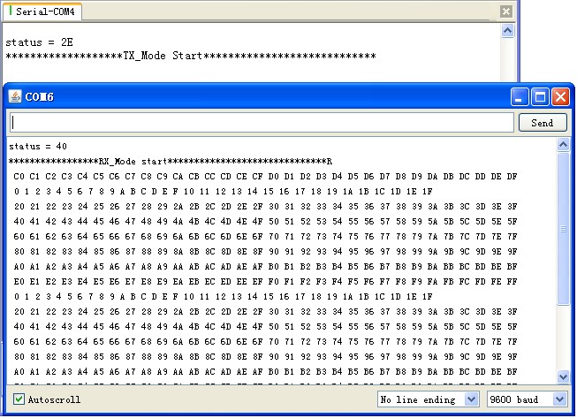
  Serial.println("*******************TX_Mode Start****************************");
  TX_Mode();                       // set TX mode
}
void loop()
{
  int k = 0;
  for(;;)
  {
    for(int i=0; i<32; i++)
        tx_buf[i] = k++;
    unsigned char status = SPI_Read(STATUS);                // read register STATUS's value
    if(status&TX_DS)                                        // if receive data ready (TX_DS) interrupt
    {
      SPI_RW_Reg(FLUSH_TX,0);
      SPI_Write_Buf(WR_TX_PLOAD,tx_buf,TX_PLOAD_WIDTH);     // write playload to TX_FIFO
    }
    if(status&MAX_RT)                                       // this is retransmit than  SETUP_RETR
    {
      SPI_RW_Reg(FLUSH_TX,0);
      SPI_Write_Buf(WR_TX_PLOAD,tx_buf,TX_PLOAD_WIDTH);     // disable standy-mode
    }
    SPI_RW_Reg(WRITE_REG+STATUS,status);                    // clear RX_DR or TX_DS or MAX_RT interrupt flag
    delay(1000);
  }
}


Download the code below into the RX Arduino (receive) – This code will drive the nFR24L01 module to receive the data that transmit form the TX module and print it to serial port.

Note, clear RX_FIFO must bellow Read_FIFO


void setup()
{
  SPI_DIR = ( CE + SCK + CSN + MOSI);
  SPI_DIR &=~ ( IRQ + MISO);
  //  attachInterrupt(1, _ISR, LOW); // interrupt enable
  Serial.begin(9600);
  init_io();                        // Initialize IO port
  unsigned char status=SPI_Read(STATUS);
  Serial.print("status = ");
  Serial.println(status,HEX);      // read the mode’s status register, the default value should be ‘E’
  Serial.println("*****************RX_Mode start******************************R");
  RX_Mode();                        // set RX mode
}
void loop()
{
  for(;;)
  {
    unsigned char status = SPI_Read(STATUS);                // read register STATUS's value
    if(status&RX_DR)                                        // if receive data ready (TX_DS) interrupt
    {
      SPI_Read_Buf(RD_RX_PLOAD, rx_buf, TX_PLOAD_WIDTH);    // read playload to rx_buf
      SPI_RW_Reg(FLUSH_RX,0);                               // clear RX_FIFO
      for(int i=0; i<32; i++)
      {
          Serial.print(" ");
          Serial.print(rx_buf[i],HEX);                      // print rx_buf
      }
      Serial.println(" ");
    }
    SPI_RW_Reg(WRITE_REG+STATUS,status);                    // clear RX_DR/TX_DS/MAX_RT interrupt flag
    delay(1000);
  }
}


Now power on both Arduino , and connect the RX one to PC via USB. Open the IDE serial port monitor , change the baud rate to 9600 bps , and you can see the data that received.

If you want to change Arduino pin connecting to module , just modify the define on the NRF24L01.h .

All the project here(include API.h and NRF24L01.h)


Download nRF24L01_Demo_For_Arduino.

Download nRF24L01_Demo_For_Arduino_v1.1.

Download NRF24L01_module.

nRF24L01 with Arduinio’s SPI Library


VN:F [1.9.13_1145]
Rating: 8.8/10 (4 votes cast)
VN:F [1.9.13_1145]
Rating: +2 (from 2 votes)
nRF24L01 Module Demo for Arduino, 8.8 out of 10 based on 4 ratings

Related Posts

ElecFreaks
«

»

17 Comments

  1. What a great web log. I spend hours on the net reading blogs, about tons of various subjects. I have to first of all give praise to whoever created your theme and second of all to you for writing what i can only describe as an fabulous article. I honestly believe there is a skill to writing articles that only very few posses and honestly you got it. The combining of demonstrative and upper-class content is by all odds super rare with the astronomic amount of blogs on the cyberspace.

    [Reply]

    admin Reply:

    We are very glad you like it. It is prised so highly by you is honor of our team and every team member.
    We are a young team, which can not be better without supports of you all. If you think ElecFreaks is helpful, you may share it with you friends. And if you have any suggestions, please let us kown.
    Thank you very much.

    [Reply]

    VN:F [1.9.13_1145]
    Rating: 0.0/5 (0 votes cast)
    VN:F [1.9.13_1145]
    Rating: 0 (from 0 votes)
  2. [...] Wireless RF Module Demo for Arduino From: nRF24L01 Module Demo for Arduino | ElecFreaks For this you need two Arduino boards and two RF modules, one to transmit and the other to receive. [...]

  3. daigoumee says:

    Keep posting stuff like this i really like it

    [Reply]

    admin Reply:

    Thank you. We will do our best.

    [Reply]

    VN:F [1.9.13_1145]
    Rating: 0.0/5 (0 votes cast)
    VN:F [1.9.13_1145]
    Rating: 0 (from 0 votes)
  4. Ross says:

    Hi,

    What range have you achieved? Indoors? Outdoors?

    Thanks,

    Ross

    [Reply]

    robi Reply:

    Hi Ross,
    the range about nRF24L01 at 1Mbps is 40m outdoor and 15m indoor.The lower rate of transmission is far more.
    If you want greater range,more information http://www.elecfreaks.com/323.html.

    [Reply]

    VN:F [1.9.13_1145]
    Rating: 0.0/5 (0 votes cast)
    VN:F [1.9.13_1145]
    Rating: 0 (from 0 votes)
  5. Keep posting stuff like this i really like it

    [Reply]

    VA:F [1.9.13_1145]
    Rating: 0.0/5 (0 votes cast)
    VA:F [1.9.13_1145]
    Rating: 0 (from 0 votes)
  6. I’m looking at your code for the nrf24l01, you made a comment:
    If you want to change Arduino pin connecting to module , just modify the define on the NRF24L01.h .
    The current NRF24L01.h pin out does not match your description…especially IRQ = 0×20?
    Thank you for your response.

    [Reply]

    VA:F [1.9.13_1145]
    Rating: 0.0/5 (0 votes cast)
    VA:F [1.9.13_1145]
    Rating: 0 (from 0 votes)
  7. Code works! thank you

    [Reply]

    robi Reply:

    That’s good news. Well done!
    And your question about define IRQ, this demo wasn’t use it but determine the state from read register STATUS’s value.
    Of course, you can modify and enjoy it.

    [Reply]

    VN:F [1.9.13_1145]
    Rating: 0.0/5 (0 votes cast)
    VN:F [1.9.13_1145]
    Rating: 0 (from 0 votes)
  8. [...] software SPI  check here. VN:F [1.9.7_1111]please wait…Rating: 0.0/10 (0 votes cast)VN:F [1.9.7_1111]Rating: 0 (from 0 [...]

  9. Nick says:

    Hello!

    I’ve got 3 modules of http://www.elecfreaks.com/store/24g-wireless-nrf24l01p-p-118.html nRF24L01P. I have Arduino Duemilanove 328P clone and Freeduino ADK board (which is Arduino Mega 2560). I tried your configuration changing RF modules few times connecting Arduino’s together. It seems that Receiver works well, I’ve got status 2E, same as on your screenshot. But Receiver always returns status=0. What should I do?

    I connect RF modules as follows: GND-GND, VCC-3v, CS – D8, CSN – D9, SCK – D10, MOSI – D11, MISO – D12, IRQ – D13.

    Are there any changes for Arduino Mega (Freeduino ADK) in the code?

    Thank you, Nick

    [Reply]

    robi Reply:

    Hi Nick,
    That a good question. Thanks for you feedback.
    The demo doesn’t work well, because of the IO there are different define between with Arduino Dumilanove 328p and Arduino Mega, which D8, D9 pin on Arduino Dumilanove board is PORTB0 and PORTB1, but on Arduino Mega is PORTH5 and PORTH6. So the code must changes the pins define for Arduino Mega(Freaduino ADK).
    And now, we have update the demo code to v1.1 that compatible with Arduino Dumilanove and Mega, get from http://elecfreaks.com/store/download/datasheet/rf/rf24l01/nRF24L01_Demo_For_Arduino_v1.1.zip.
    Please try it again.
    If you still have any problems, please feel free to contact us.
    Good Luck!

    [Reply]

    VA:F [1.9.13_1145]
    Rating: 0.0/5 (0 votes cast)
    VA:F [1.9.13_1145]
    Rating: 0 (from 0 votes)
  10. Nick says:

    Thank you for prompt answer and fix, all my 3 modules worked fine with updated library and same wiring!

    Reading through datasheet I tried to set registers to lower datarate (and extend range) to 256K like this:
    SPI_RW_Reg(WRITE_REG + RF_SETUP, 0×27);
    Is this right setting for 256K speed? I saw that you’ve set RF_PWR register to 0 dbm for the transmitter. Will setting RF_PWR to -18dBm allow to extend range?

    Is it possible to transmit/receive data on different pipes simultaneously?
    I have few spare RF antenna connectors, is to possible to solder this connectors to internal antenna and have extended range like nRF24L01p+PA+LNA?

    Thank you!

    [Reply]

    robi Reply:

    That’s a good news!
    Frist, SPI_RW_Reg(WRITE_REG + RF_SETUP, 0×27) setting for 256Kbps. Yes, and you setting the RF_PWR to 0dBm at the same time.

    Second, setting RF_PWR to -18dBm will allow to shorter range. Maybe you should setting ox2o to RF_SETUP for testing.

    Third, the nRF24L01 support 6 data pipe, duplex communication can be achieved.

    At last, solder a extend antenna, I think you’d better not to do. Then antenna’s length been customize and calculated many times. The antenna is not longer the better.

    [Reply]

    VN:F [1.9.13_1145]
    Rating: 0.0/5 (0 votes cast)
    VN:F [1.9.13_1145]
    Rating: 0 (from 0 votes)
  11. [...]     程序参考的http://www.elecfreaks.com/203.html 我在主程序中修改了几个地方,使得通信中断后,能重新初始化。 [...]

Leave A Reply


Go To Top ↑

Powered by ElecFreaks