


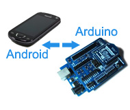
Communication between Android and Arduino with Bluetooth(2)

Preface
First, if you don't kown what is ADK(Android Open Accessory Development Kit). From now on, we provided to you Freaduino ADK (A new board has just been made by us this week, which is a Android Open Accessory Development Kit compatible board, but not a simple clone of it.) To make the communication between Android and Arduino easy, we would like show you a new way that Android interact with Arduino and other similar boards by Bluetooth. From here, you will see how to connect Android and Arduino with Bluetooth Bee. You will find it's not difficult any more after reading this post. There also is a post about the APP we made last week, which will be used in the following. If you want to know the details of this Android's APP, please read this post: Android+BlueTooth(Part1).
Preparation
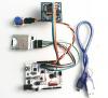
Before we getting start, there are some modules must be prepared. As the figure1,of course an Android phone and Arduino main board, then a Bluetooth Bee Module and a XBee Shield which compatible with Bluetooth Bee. It's pretty good if you own them, otherwise you can get them from our store in a low cost: Bluetooth Bee($23), XBee Shield($15), Arduino main board. From now on, there is more easy module instead of XBee Shield is Bluetooth Shield($23), which has integrated of Bluetooth module. Then about the Software, you are able to get the APP from here.

Figure 1
How to Communication
The XBee shield provides 3 optional hardware interface, which determine how the shield's serial communication connects to the serial communication between microcontroller (ATmega8 or ATmega168) and FTDI USB-to-serial chip on the Arduino board. So it is necessary to explain the XBee shield work mode first. The XBee shield has 4 row jumpers figure2. DIN corresponds with Bluetooth Bee's RX, DOUT corresponds with Bluetooth Bee's TX, TX_H corresponds with Arduino's TX(D0), RX_H corresponds with Arduino's RX(D1), D2 corresponds with Arduino's D2, D3 corresponds with Arduino's D3. We select work mode by DIN and DOUT freedom match with TX_H, TX_H, D2, D3. 
Figure 2
Bluetooth Bee direct use Arduino main board's UART(TX/RX) connect to PC. However this method must remove the MCU chip, and the Bluetooth Bee inserted on Arduino's main board with XBee shield. This means the Bluetooth Bee direct connect to PC Serial port. Setting the XBee shield's jumper connect as below: DIN to RX_H , DOUT to TX_H.

Figure 3
Previous work done, power on the Arduino board and the Bluetooth Bee's LED1 will blink, and the PC will find a new serial port hardware, and we are COM6 here.

Figure 4
So, we can use a serial port tool to control Bluetooth Bee module, user can send the AT command to the module to set the control parameters and send control order. Bluetooth Bee is base on HC-05/HC-06. HC-05 has three work roles (Master, Slave and Loopback) at the automatic connection work mode. HC-06 only has Slave mode.
Note: In this post, Bluetooth Bee means HC-05, because there is more flexible control and all HC-06's feature in HC-05. Bluetooth Bee default mode is AT module, the baud rate of which is 38400. If you want to get AT module, you should set work mode. After power on then input the Bluetooth Bee's pin20 to high level, then the module will enter to AT module. At this time, the baud rate is 38400. You can get the AT command from here. About the tool to choose the serial port, SecureCRT is a nice choice. However AT command should end up with "\r\n". It means when you finish programming, you should add terminator (“ENTER” or “0x0d 0x0a”) to the program. So you need setting SecureCRT end up "\r\n", there are some other choices, we recommend sscom32E.exewhich provided by us and automatically added "0x0a 0x0d" in end of command. No matter what you are going to use the serial port tool, please remember command end up "0x0a 0x0d". Bluetooth Bee Master mode, it means the module will active search for remote Bluetooth devices, so the Android APP will be Server. The Slave mode is the mode just be discovered by other Bluetooth devices and be connected, so the Android APP will be Client. OK, the specific steps they are connected as below:
step 1: Install and Choose the Bluetooth APP on the Android phone

Figure 5
step 2: Click the "Bluetooth Bee" App

Figure 6
step 3: Click the "Open Bluetooth" enable Bluetooth to make it discoverable. There a dialog box will appear and request user permission to enable Bluetooth. Select "Yes" and the system will enable Bluetooth and focus will return to your application once the process completes (or fails). "Yes" returns RESULT_OK and "No" returns RESULT_CANCELED.

Figure 7
step 4: Click "AS Server", will wait for other Bluetooth devices pair request.

Figure 8
step 5: Android side gets all ready. Now we start setting Bluetooth Bee. Because the App is Server mode, the Bluetooth Bee should be selected Master mode. Connect Bluetooth Bee's pin20 to hight level, and then send "AT" to the module by serial port tool which baud rate is 38400, data bit is 8, stop bit is 0, check parity is 0. Bluetooth Bee accept "AT" will return OK, it will show you have entered the AT mode. You can send the various command for query or setting. As figure 9.

Figure 9
step 6: After entered AT mode, select Master mode by setting as below: at+role=1\r\n //Setting Master mode return OK at+init\r\n //Initialize the SPP profile lib( can’t repeat initialization) return OK at+iac=9e8b33\r\n //Inquire Bluetooth device has an access code return OK at+inqm=1,9,48\r\n //Inquire mode: 1) has the RSSI signal intensity indication, 2) stop inquiring if more than 9 Bluetooth devices response, 3) limited time in inquiring is 48*1.28=61.44s. return OK At+inq\r\n //inquire the Bluetooth devices around return : +INQ:2:72:D2224,3E0104,FFBC +INQ:1234:56:0,1F1F,FFC1 +INQ:F4FC:32:4F4982,58020C, 7FFF ...

Figure 10
//Make pair with the remote Bluetooth device( address:F4FC,32,4F4982), the limited time is 20s. Default pair password is 1234. At+pair=F4FC,32,4F4982,20\r\n

Figure 11
return OK at+fsad=F4FC,32,4F4982\r\n \\To check whether the Bluetooth device (address: F4FC,32,4F4982) is in the pair list. return OK at+link=F4FC,32,4F4982\r\n \\The Bluetooth device (address: 12:34:56:ab:cd:ef) is in the pair list. The connection can be built directly without inquiring. return OK If it returns OK, Congratulation!! We have linked Android Blutooth and Bluetooth Bee, the next step of course send some data for test. We can send data by serial port tool, as figure 12. I think there are really so many things you can do by the Bluetooth Bee module communicate with Android App.

Figrue 12
However, it's just Single-income-single, do you want a Full-duplex communication? If "Yes", we will say: OK, it's no problem! We have made the demo through Android App "As Client" and Bluetooth Bee as Slave mode to realize it.
Step 1: First, you should disconnect the link Android and Bluetooth Bee, So you need release Bluetooth Bee pin20 to low and then input to AT mode again, and then send 'at+disc\r\n', return OK. The other way, you can cut off the power :) . Now, we should set Bluetooth Bee to Slave mode, so send 'ad+role=0\r\n', return OK. Reset the power, the module is Slave mode. This mode just could be connectted. To communicate with each other, you don't have to insert to AT mode again, just normal mode you can accept and send data by serial port tool.
Step 2: Click "Open Bluetooth" and then Click "AS Clent", it will search the remote devices and return the device's address.

Figure 13
Step 3: Click one address to pair and connect, if connection succeed it will return to the menu as Figure 14

Figure 14
Step 4: We can send and accept data to each other. The App we have modified to Full-duplex communication, could send and receive data simultaneously. In the end of the post you can get the full code. 
Figure 15
Second way, Oh my god, it is too long and too boring?Just relax and take a break. The second way, setting the XBee shield's jumper connect: DIN to TX_H , DOUT to RX_H. Note that the RX and TX pins of the microcontroller are still connected to the TX and RX pins (respectively) of the FTDI chip - data sent from the microcontroller will be transmitted to the computer via USB as well as being sent wirelessly by the Xbee module. The microcontroller, however, will only be able to receive data from the Xbee module, not over USB from the computer. So this way just for you has perfect code and don't need monitor from serial port, because you cann't see anything from serial port tool.

Figure 16
Third way, use Software Serial library to define D2 and D3 as a virtual serial port TX and RX. By this way, you can use Arduino's Serial Monitor to Monitor operation of the code. Setting the XBee shield's jumper connect: DIN to D3, DOUT to D2. And you can change the define in the code. There are also some character conversion issues, maybe you can solve it. If you do it, please share with us.

Figure 17
[cce_cpp]
/*********************************************************************
**  Description:                                                    **
**  This file is a sample code for your reference.                  **
**                                                                  **
**  Copyright (C) 2011 ElecFreaks Corp.                     	    **
**  Created by ElecFreaks Robi.W /10 June 2011                      **
**                                                                  **
**  http://www.elecfreaks.com                                       **
*********************************************************************/
#include

#define rxPin 2
#define txPin 3

SoftwareSerial mySerial =  SoftwareSerial(rxPin, txPin);

void setup()
{
  // define pin modes for tx, rx, led pins:
  pinMode(rxPin, INPUT);
  pinMode(txPin, OUTPUT);
  mySerial.begin(38400);
  Serial.begin(9600);
}

void loop()
{
  // listen for new serial coming in:
  char someChar = mySerial.read();
  // print out the character:
  mySerial.print(someChar);
  // print to Serial Monitor
  Serial.print(someChar);
}
[/cce_cpp]

Conclusion
That is all about how to communicate Android with Bluetooth Bee. The demo is a Bata version, just a sample code for your reference. We will gradually enrich it and you are appreciated to redistribute and/or modify it, and please share it with us.
Reference:
About the Author


How to Send Micro:bit Data to ThingSpeak IoT Platform
January 11, 2018
VC0706 Camera Module DIY Guide
December 18, 2014

nRF24L01 Module Demo for Arduino
May 6, 2011


Children’s Programming Education is the Future Trend
March 20, 2024


ELECFREAKS AI Smart Lens Now Compatible with Gigo Building Blocks!
February 21, 2024


Comments