

Micro: bit Fundamental Course–Button&Display
January 9, 2019
Make an Intruder Detection with Micro:bit
January 9, 2019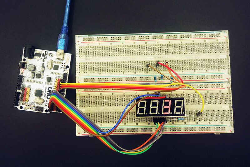
In our latest blog “Start&End Kit: LED Drive Principle“we have learned LED drive principle about digital tube, today we are going to do an interesting experiment about Arduino digital tube with knowledge we learned in previous chapter. To start our experiment, we have to gather some tools and materials. I have made a list for you.
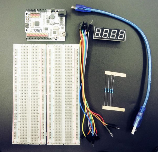
Tools & Materials:
Arduino UNO
Jumper Wire
Mini USB Cable
Breadboard
4-bit, 7-segment Common Cathode Digital Tube X1
430???Upright Resistance X4 (390Ω~1K???are ok too)
Several Jumper Cable for Experiment
After we gathered these tools and materials, we can move on to our experiment. You can follow the procedure and move your hands with me.
Procedure
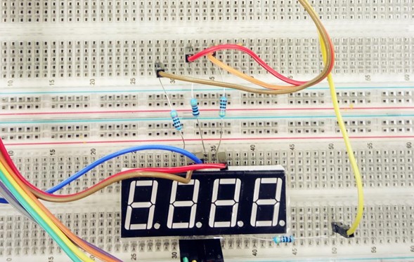
Step 1: Pick up material we need for experiment, see picture below:
Step 2: Hardware Connection We have to connect digital tube to Arduino UNO board by jumper wire. Footer a: connect to Arduino UNO D0; Footer b: connect to Arduino UNO D1; Footer c: connect to Arduino UNO D2; Footer d: connect to Arduino UNO D3; Footer e: connect to Arduino UNO D4; Footer f: connect to Arduino UNO D5; Footer g: connect to Arduino UNO D6; Footer dp: connect to Arduino UNO D7;
Note: Footers are pins on digital tube.
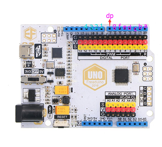
4 common port connection on digital tube: (A resistance is needed between 4 common ports and Arduino UNO to limit current.So we use upright resistance we prepared before.)
Footer
1: connect to Arduino UNO D8; Footer
2: connect to Arduino UNO D9; Footer
3: connect to Arduino UNO D10; Footer
4: connect to Arduino UNO D11;
Note: Footers are pins on digital tube.
If you are still not very clear, you can refer to picture below. I made this picture for easier understanding.
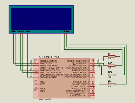
Now, have you finished connection? If you completed, you can enter into next step and make a program.
Step 3: Edit Program Open Arduino IDE interface, copy and paste the code below into editor area.
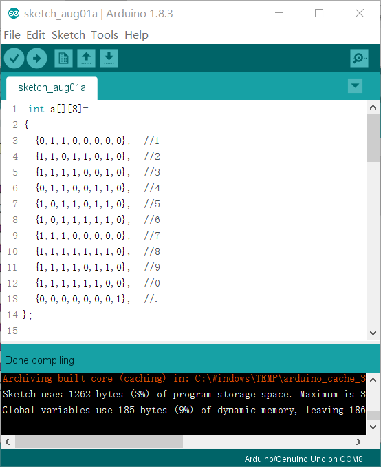
[cc_cpp]
int a[][8] =
{
  {0, 1, 1, 0, 0, 0, 0, 0}, //1
  {1, 1, 0, 1, 1, 0, 1, 0}, //2
  {1, 1, 1, 1, 0, 0, 1, 0}, //3
  {0, 1, 1, 0, 0, 1, 1, 0}, //4
  {1, 0, 1, 1, 0, 1, 1, 0}, //5
  {1, 0, 1, 1, 1, 1, 1, 0}, //6
  {1, 1, 1, 0, 0, 0, 0, 0}, //7
  {1, 1, 1, 1, 1, 1, 1, 0}, //8
  {1, 1, 1, 1, 0, 1, 1, 0}, //9
  {1, 1, 1, 1, 1, 1, 0, 0}, //0
  {0, 0, 0, 0, 0, 0, 0, 1}, //.
};

void setup() {
  // put your setup code here, to run once:
  for (int i = 0; i < 12; i++) {
    pinMode(i, OUTPUT);
  }
}

void loop() {
  // put your main code here, to run repeatedly:
  for (int wei = 8; wei < 12; wei++)
  {
    digitalWrite(wei, HIGH);
  }
  int dwei = 8;
  int shi = 600;
  int m = 0;
  while (1)
  {

    for (int k = 0; k < 4; k++)
    {
      int pin = 0;
      dwei = k + 8;
      digitalWrite(dwei, LOW);

      for (int s = 0; s < 8; s++)
      {
        digitalWrite(pin, a[k][s]);
        pin++;
      }
      delay(shi);

      digitalWrite(dwei, HIGH);
      pin = 0;
      for (int s = 0; s < 8; s++)
      {
        digitalWrite(pin, LOW);
        pin++;
      }
      if (shi < 210)
        shi = shi - 5;
      else
        shi = shi - 50;
      if (shi < 6)
      {
        shi = 1; m++;
        if (m == 1000)
        {
          m = 0;
          shi = 600;
        }
      }
    }
  }
}
[/cc_cpp]
Step 4: Operate Program Connect Arduino UNO board to computer with a USB cable, and download code, then you will see the picture below.
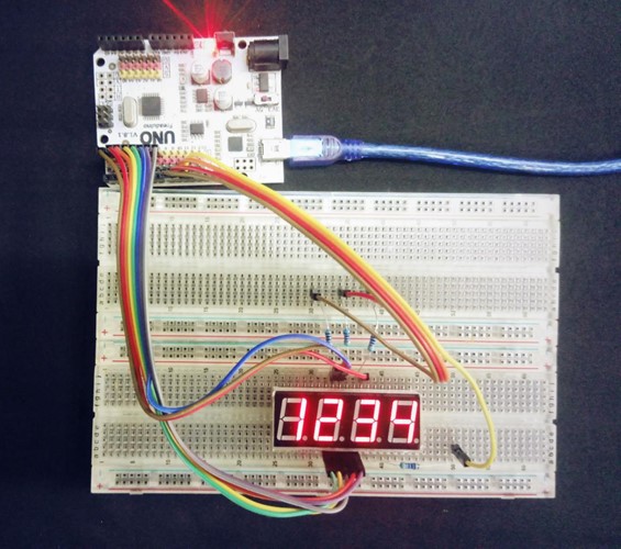
 Now
Now
can you do this experiment by yourself? Isn’t it very simple and easy? Just move your hands and have a try!
Abstract
This article will show you an interesting experiment about LED digital tube display. It requires you to use knowledge you have learned about LED drive principle. If you have controlled this principle well, then you can create more funny gadgets like a DIY clock.