

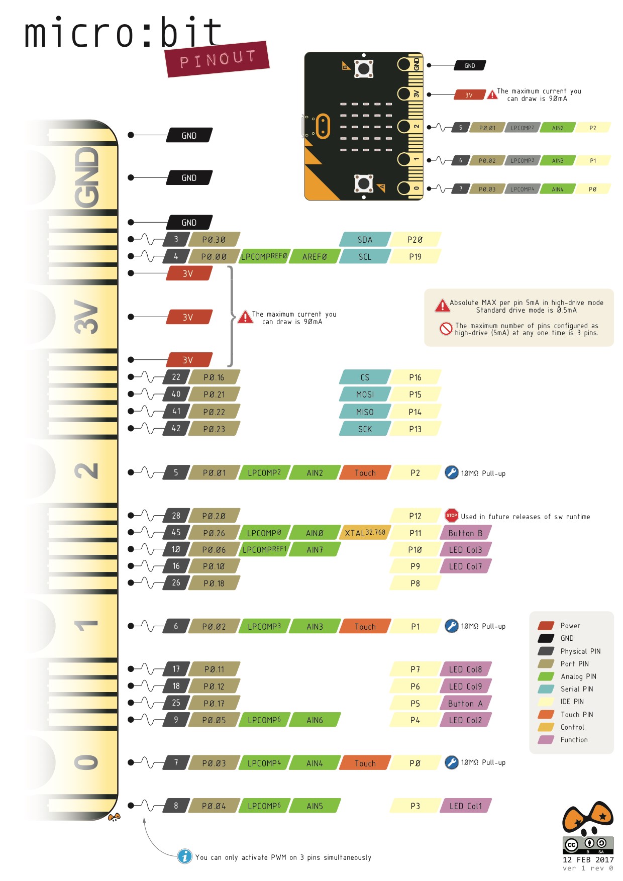
Master Your Micro:bit with Arduino IDE–Button and Other GPIO
January 7, 2019
Friday Product Post: Micro:bit Accessories
January 7, 2019
HC-11 433MHz Wireless RF Transceiver Module with Spring Antenna (abbreviated to HC-11???/span>is a new version of multi-channel embedded wireless transmission module. Radio frequency is 434.4—439.0MHz. It can set multiple channels.Step is 400KHz, with 20 channels in total.The maximum transmit power is???/span>10dBm???/span>, with 40m communication distance in wide open areas.
Version
HC-11 V1.9
Specifications
Long communication distance???/span>About 100 meters at default setting???/span> Operating frequency range???/span>434.4—439.0MHz???/span> Transmit power???/span>max: 10dBm???/span> Power supply voltage???/span>DC 3.2V ~5.5V???/span>
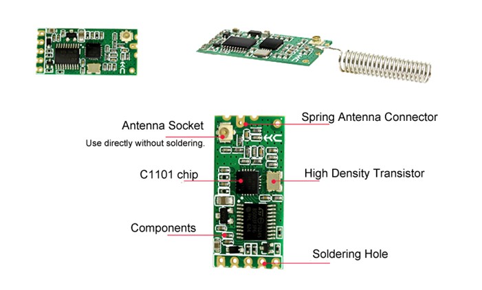
Product Introduction
HC-11 wireless RF UART communication module is a new generation of multi channel embedded wireless data transmission module. Radio frequency of 433.4 – 439.0MHz, can be setting communication channel, step is 400kHz, a total of 20 channels. The module maximum transmit power is 10mW (10dBm), communication distance about 100 meters. The module adopts a stamp hole encapsulation method, which can be welded. The module size is 27.4mm*13.2mm *4mm (including antenna seat, not including the spring antenna), which is convenient for the customer to be embedded in the application system. The module has a PCB antenna seat ANT1, users can use the coaxial cable, the use of 433MHz band external antenna. The module also has antenna welding hole ANT2, convenient user welded spring antenna. The user can choose one kind of antenna according to the request. The module contains MCU, users do not need to program in addition, just send and receive UART data. The module uses a variety of UART transmission mode, the user can choose according to the requirements of the use of AT command. The four UART modes of FU1, FU2, FU3, FU4, the average operating current is 3.5mA, 80μA, 22mA and 22mA, the maximum operating current is 40mA (full power transmit state).
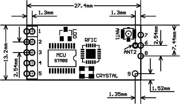
Product Size
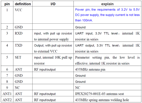
Pin definition
The HC-11 module consists of 9 pins and a RF antenna block ANT1, which is defined as the following table:
Pin1- 6 have two pads each, by the outside of the half hole pad for the patch welding. Pin 6 on the inside of the pad ANT2 for module chip welding, you can hand welding spring antenna. Pin 1 – 5 by hole inside the pads used for welding 2.54mm row spacing, can be plugged directly into the user PCB row seat.
Wireless UART Transmission
1. Brief introduction of the working principle
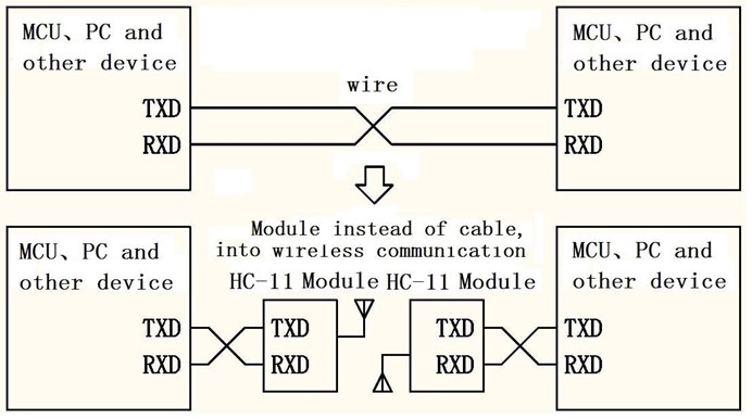
As shown in the figure above, the HC-11 module is used to replace the physical connection in half duplex communication. On the left side of the device to send UART data to module, the module’s RXD port after receiving the UART data, the data automatically transmitted to the air in the way of radio. On the right side of the module can automatically receive, and restore the original left device from the TXD UART data send. From right to left is the same. Module can only work in half duplex state, can not send and receive data at the same time.
2. UART transparent transmission characteristics
HC-11 module has four UART transparent transmission mode: FU1, FU2, FU3 and FU4. When in use, various modes are just to send and receive UART data can be, without air wireless transmission part, but only in the same air baud rate can communicate with each other under the sky! The system default in FU1 full speed mode. Different mode can not transmission data each other, the user can choose the best mode according to the actual situation. Modules are generally used in pairs to transmit data to each other in half duplex mode. At the same time, the UART transparent transmission mode, the baud rate, the wireless communication channels must be set the same. Factory default is set to FU1, 9600bps (8 bits data, no parity, 1 stop bit), CH001(434.4MHz), A000(module address), P8(transmit power: +10dBm). The number of bytes send to the module UART port is generally not limited in use. But in view of the environmental interference and other factors, a continuous transmission of a large number of data, it is possible to lose some of the bytes. So, it is best to have a answer response and retransmission mechanism, to avoid the loss of information.
3. The four kinds of UART transparent transmission mode
HC-11 module UART transparent transmission mode default is FU1. FU1 mode is more power saving mode, at this time, the idle work current of the module is about 3.5mA. This mode can also set up 8 kinds UART baud rate(1200???/span>115200bps), but the air baud rate is same. FU2 mode is power saving mode, at this time the module idle work current is about 80μA. This mode module supports only 1200 bps, 2400 bps and 4800 bps UART baud rate, short communication distance. This mode, only the transfer of a small amount of data (each packet within 20 bytes), packet transmission time interval can not be too short (preferably in more than 2 seconds), otherwise it will result in data loss. In addition, due to the delay is relatively long, when UART data send to the module, a maximum of only 245 bytes of data. FU3 mode is full speed mode, this module idle working current is about 22mA. In this mode, the transmission delay time is short. FU4 model is adjustable distance communication mode, the UART baud rate set too low, the communication distance is farther, but the transmission delay will be lengthened, especially below 9600 bps, a question and answer, and may need more than 300mS. Here are some of the characteristics of the reference value of a variety of modes:
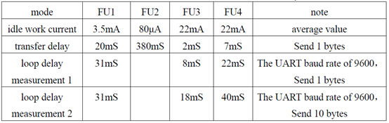
Note: the test loop delay is short circuit the module of the TX and RX pins, sending UART data to another module, sending UART data to another module of TX pin for this period of time to return to the data from the beginning.
MANUAL Module Parameter Setting AT command
AT command is used to set the parameters of the module and switch the function of the module. At the same time, the parameters and functions of the modification, power off will not be lost.
1. To enter into the AT command mode
The first entry way – the normal use (already on the power), the fifth pin “SET” set the low level. Second entry way – power off, the fifth pin “SET” connect to ground (low level), then power on. These two ways can make the module into the AT command mode, release (“SET” pin is not connected to the low level) then exit the command mode. After exiting the AT command mode, if you change the function of the module, you will be cut to the corresponding functional status. Second ways to fix the 9600, N, 1 of the UART format into the command mode. Note: after the withdrawal of the AT command mode, the module is in a reset state, at least wait for 200mS before entering the AT command mode again, otherwise the module may into the AT command mode in second way!
2. Command explain
a. AT
Test command Example???/span> Send the module command “AT”, module returns “OK”.
b. AT+Axxx
Change module address command. Can set the address between 000~255. Factory defaults to 000. Example???/span> Setting module address 012, please send the module command “AT+A012”, module returns “OK012 “.
c. AT+Bxxxx
Change the UART baud rate command. Can set the baud rate of 1200bps, 2400bps, 4800bps, 9600bps, 19200bps, 38400bps, 57600bps and 115200bps. Factory defaults to 9600bps. Example???/span> Setting module UART baud rate is 19200bps, please send the module command “AT+B19200”, module returns “OK-B19200”.
d. AT+Cxxx
Change the channel of the wireless communication, from 001 to 127 (note: more than 20 after the wireless channel, may not communicate). The default value of the wireless channel is 001, and the working frequency is 434.4MHz. The step of the channel is 400KHz, the frequency of channel 20 is 439.0MHz. Example???/span> Set the module to work to channel 20, please send the module command “AT+C020”, the module returns “OK-C020”. After exiting the AT command mode, the module works in the channel 20, and the operating frequency is 439.0 MHz.
e. AT+FUx
Change module UART transparent transmission mode, there are FU1, FU2, FU3 and FU4 four modes. Module default mode is FU1, the UART transparent transmission mode of the two module must be set to the same as the normal communication. Please see the above “wireless UART transparent transmission” section of the introduction. Example???/span> Send the module command “AT+FU3”, the module returns “OK-FU3”.
f. AT+Px
Set the transmit power level of the module, the x is 1-8, the module corresponding transmit power is as follows:
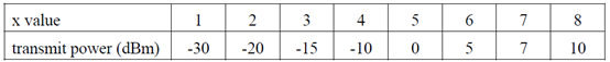
Default setting is 8,the transmit power is the biggest, the communication distance is the most distant. In general, the transmit power per drop 6~10dB, communication distance will be reduced by half. Example???/span> Send the module command “AT+P5”, the module returns “OK-P5”. After exiting the AT command mode, the module transmit power is 0dBm.
g. AT+Ry
Acquisition module of the individual parameters. y for A, B, C, F, P in any of the letters, respectively: address, baud rate, communication channel, transmission mode, transmit power. Example 1: Send the module command “AT+RA”, if the module returns “A000”, then query to module address is 000. Example 2: Send the module command “AT+RB”, if the module returns “B9600”, then the UART baud rate is 9600bps. Example 3: Send the module command “AT+RC”, if the module returns “RC001”, then the communication channel is 001. Example 4: Send the module command “AT+RF”, if the module returns “U1”, then check the module to work in the UART transmission mode 1. Example 5: Send the module command “AT+RP”, if the module returns “P8”, then the module’s transmit power is +10dBm.
h. AT+RX
Get all parameters of the module. In order to return to the UART transmission mode, UART baud rate, communication channel, module address, transmit power and other information. Example: Send the module command “AT+RX”, the module returns”U1\r\n B9600\r\n C001\r\n A000\r\n P8\r\n”. (“\r\n” is CRLF)
i. AT+Uxxx
Set the data bits, parity bits and stop bits of UART communication. In the parity check bit, N represents the non parity check, O represents the odd parity check, E represents the even parity check. Stop, 1 on behalf of the 1 stop bit, 2 on behalf of the 2 stop, 3 on behalf of the 1.5 stop bit. Example: To set the UART communication format to 8 data bits, odd parity, 1 stop bit, please send the module command “AT+U8O1”, the module returns “OK-U8O1”.
j. AT+V
Query module firmware version information, return the official website address and firmware version. Example: Send the module command “AT+V”, the module returns “HC-11_V1.9 “.
k. AT+SLEEP
AT+SLEEP After receiving the command, the module enters the sleep mode when exiting AT command mode, the operating current is about 22μA, and the module can not carry on the UART data transmission. Once again into the AT command mode state, the module automatically exit the sleep mode. Example: When no wireless data transmission, in order to save energy, you can send the module command “AT+SLEEP”, the module returns “OK “.
l. AT+RESET
The UART baud rate, UART communication channel, module address and transmit power restore factory default. Example: Send the module command “AT+RESET”, the module returns “RESETT_OK “, restore the factory default value. The UART baud rate of 9600bps, C001 UART communication channel, the module address is A000, transmit power is P8 (+10dBm).
Note
1. Do not directly connect the light emitting diode and resistor between the TX and the power supply side of the module, otherwise it may affect the module UART communication.
2. Using MCU to dynamically modify the module parameters, set the module fifth pin “SET” low level, need to wait for the 30ms to send AT command to the module. Set the fifth pin “SET” high level, need to wait for the 50ms to enter the UART transmission mode.
3. If the distance between modules is very close (<0.2 meters), it is best to set the two module transmit power to a lower value, such as P1-P3. Otherwise, sometimes receive saturation, so module communication failure.
Application Example and Circuit
HC-11 module connect to the computer/MCU UART port
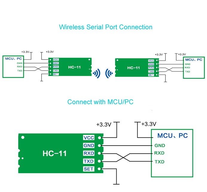
“SET” pin through the switch SW1 grounding can enter the parameter setting state, left hanging out.
Application: FreaksBot Bluetooth Car