


Arduino Starter Kit
January 11, 2019
Installation Guide For Tiny
January 11, 2019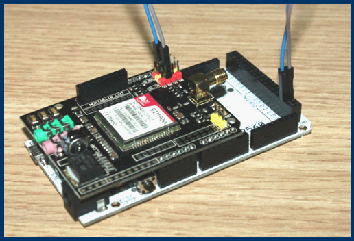
Hi, friends, we persistently received emails seeking for technical support, in particular, the product of EFCom. To better serve the customers, we spent much time completing the quick starter guide and the data sheet of EFCom, from which enthusiasts are available to elaboratively comprehend the specifications and the operation steps of product. We will also launch video to enrich the tutorials and add more useful materials to wiki in the near future. Currently let’s go ahead to see quick starter guide.
EFCom Introduction
GPRS Shield-EFCom is a serial GSM/GPRS wireless module, compatible with all of Freaduino and standard Arduino boards. Only connecting EFCom with these boards ,enables you to easily control EFCom via AT commands, dialing a phone, sending a message ……Besides, EFCom supports LCD5110 display and serial Keypad input。It has been extensively used in a variety of fields, helping Arduino hobbyists promptly to acquire GSM/GPRS mobile phone research,suitable for wireless development projects,also applying to remote control development.
Step 1. Hardware Preparation

- Power adapter ×1 (supply current>800mA)
- EFCom ×1
- Arduino UNO ×1
- SIM card ×1(make sure SIM card is unlocked???/span>
- Antenna ×1
- USB cable ×1
Step 2. Software Preparation
1. Arduino IDE 1.0.x
2. Serial Tool-sscom32
Step 3. Hardware Operation
- Install the SIM card into your GPRS Shield.
- Take an Arduino board and install the GPRS Shield over it.
- Connect the antenna to the GPRS Shield.
- Connect the Arduino to your computer using a USB cable.
- Plug the power adapter to Arduino.
- Press and hold the power button a short while(Over 3 seconds) on the GPRS Shield to turn it on. Wait half a minute for the GPRS Shield to connect to the network (NET LED will start blinking every 3 seconds or so). If it continues blinking every 800mS, which means EFCom can’t connect to the Internet, please pull the SIM card and re-plug it., or try another card.
Step 4. Software Operation
1.Copy and paste our identifying code “Demo1.txt” from GPRS Shield-EFCom\Wireless\Wiki (If you use Arduino1.0,please copy and paste Demo2.txt),and then compile it until the software displays“done compiling”, which means this operation succeeded.
2.Upload the identifying code until the software displays“ done uploading”, which means uploading succeeded.

3.Type and send “AT” (without the quotes) followed by carriage return (enter key) to the Arduino board. The GPRS Shield should respond by sending back an “OK”. This would mean that you have been able to successfully control your GPRS Shield with various AT Commands.
Please note the circled places and choose Baud Rate as 19200 8-1-N-0 ,in addition, select the corresponding COM.
4.Send a message. Through your serial terminal software, send AT+CMGF=1 and press the Enter key.The GPRS Shield will respond with an OK. Send AT+CMGS=”+86158×× ×× ×× ” and press the Enter key (include the quotes) and The GPRS Shield will send a >signaling you to start typing the message. Start typing your message and when you are done, press Ctrl + Z keys on your keyboard.The modem will accept the message and respond with an OK. A few moments later, the message should be received on the handset whose number you had specified.
5.Call a phone .Through your serial terminal software, input “ATD158 ××××××;” and the GPRS Shield will respond with an OK. Congratulations on your success of dialing a phone.
Q & A
Q : EFcom Shield IO is not sufficient,and can you supply other spare IO ???/p>
A : EFcom itselef does’t spare IO???but users can apply LCD5110 data port from D8 to D13. Besides, imitated IO A5 is for serial keypad,so users can also directly put it into use.
Q : Can EFcom Shield be worked over Mega2560???/p>
A :Yes, but jumper wires are needed to connected to D18/D19 .Or you can use hardware serial port D10/D11, because Mega2560 can’t use D2/D3 as software serial port. Mega2560 has special requirements for software serial port, and detailed description is demonstrated as below.
[cce]
 // Specifically for the Arduino Mega 2560 (or 1280 on the original Arduino Mega)
 // A majority of the pins are NOT PCINTs, SO BE WARNED (i.e. you cannot use
    them as receive pins)
 // Only pins available for RECEIVE (TRANSMIT can be on any pin):
 // (I've deliberately left out pin mapping to the Hardware USARTs - seems
    senseless to me)
 // Pins: 10, 11, 12, 13,  50, 51, 52, 53,  62, 63, 64, 65, 66, 67, 68, 69
   #define 	rxPin 	19
   #define 	txPin 	18
[/cce]
