Micro:bit Fundamental Course:Music
January 9, 2019
Micro:bit Fundamental Course: Touch Button
January 9, 2019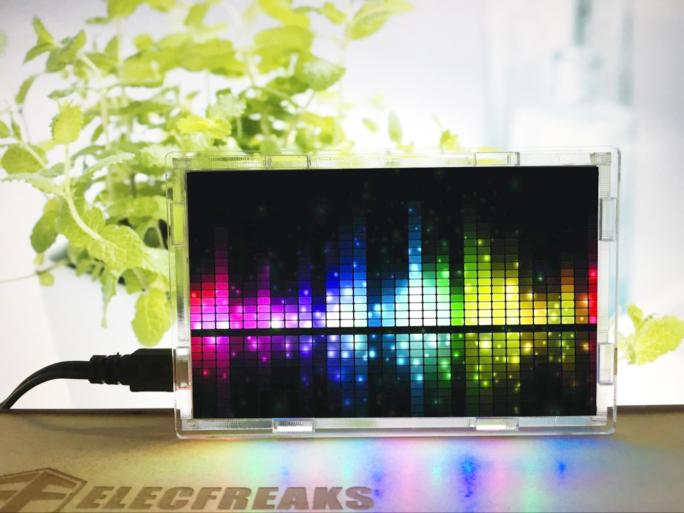
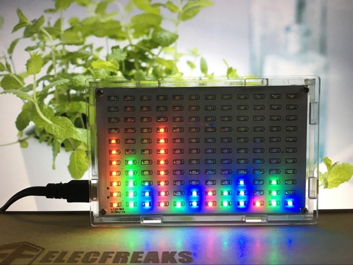
LED Music Frequency Spectrum Display Soldering Kit is a set of components which can form an LED Music Frequency Spectrum Display. This display can show us music frequency with LED light bars while broadcasting a piece of music.That means you can use it as a loudspeaker as well as music frequency display. Before we goes deeper into our product, let’s take a look at a picture of completed one:
Very beautiful right? This LED Music Frequency Spectrum Display have a specified audio frequency drive core with multiple decode algorithm. It has multiple working mode selections catering for your requirements. The performance is good due to its simple circuit design. The biggest feature of this display is that it owns LED dot metric display. It can use 2 channels to control LED display. The 2 channels are: single voice channel and dual voice channel. When it is in single voice channel, LED dot metric becomes 12*11. While in dual voice channel, LED dot metric array turns to left 6*11 and right 6*11. From this, we can see that single voice channel can display more frequency spectrum. Besides, it have memory function which can preserve parameters set by users forever. With these features, it become a good product for us to play or broadcast music or radios. Then, how can we make one? First, you can click here to get a set of kit. Then we can go on our DIY assembly course. You can follow the steps below.
Step1 : Solder LED Light
Pay attention to the polar. The picture below showed negative point. LED bead of each color can be welded in any place.
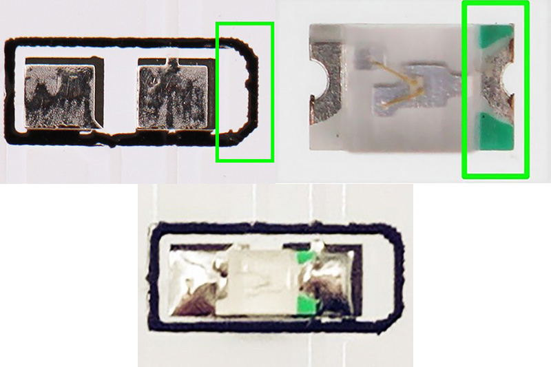
Welding Completed:
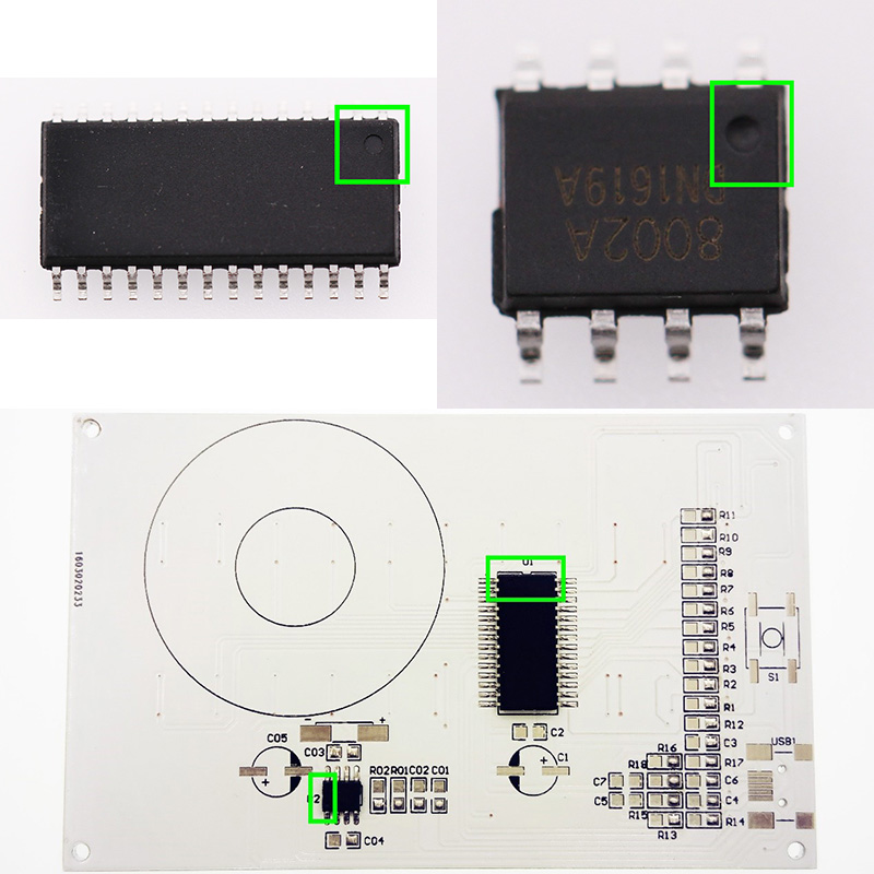
Step 2 : Solder IC
The small round spot corresponds to the concave part on PCB IC welding plate.
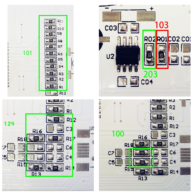
Step 3 : Solder Resistance
Step 4 : Solder Mount Capacitor
(1uf has bigger volume than 0.1uf) 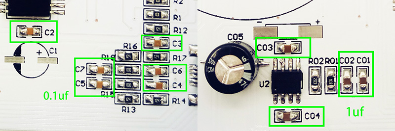
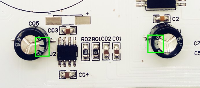
Step 5: Solder Electrolytic Capacitor
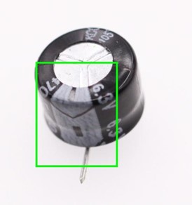
Note: Capacitor has positive and negative point. The mark in the above picture is negative point. Electrolytic capacitor has a white line. The footer is comparatively shorter.
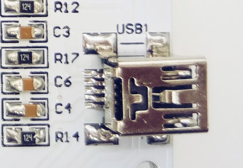
Step 6: Solder USB socket.
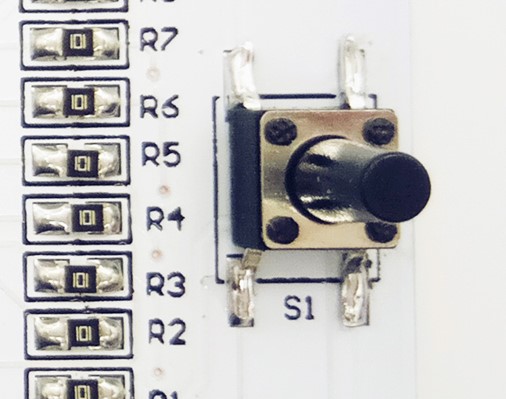
Step 7: Solder Switch
Switch has no positive or negative point
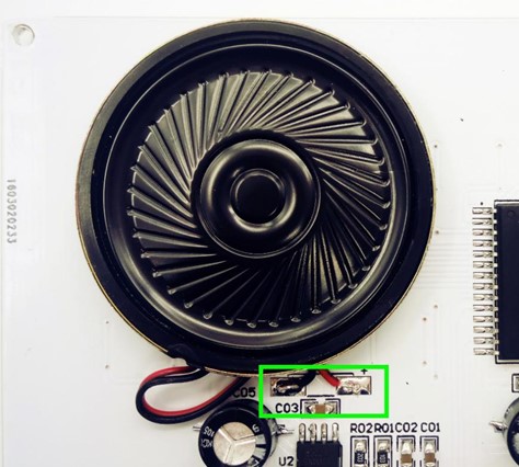
Step 8: Solder Speaker
Pay attention to positive and negative point.
Step 9: Install shell
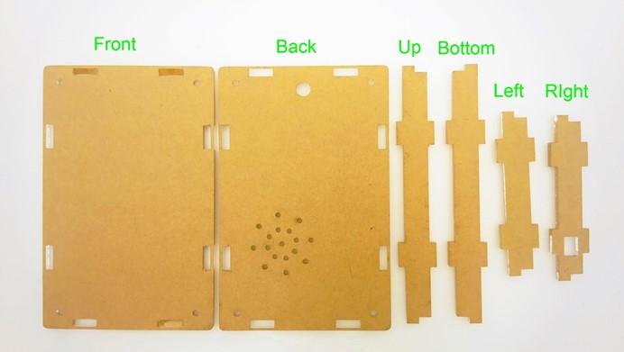
Completed Installation Once we completed installation, we can connect our artwork to our mobile and play a music to see what will display. We can see the LED light is dancing on the panel with the music just like the picture below. Isn’t it wonderful and amazing?