

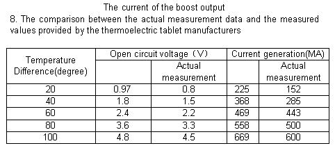
Thermoelectric Power Generation user guide
January 11, 20199DOF Module with Processing
January 11, 2019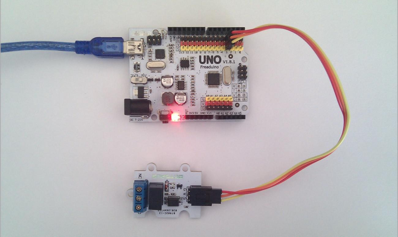
Believe that many people still remember our recently-updated new product OCTOPUS 1Channel Relay, which inherits unique outlook design and the standard 3Pin interface from our series of Octopus products, delicate and easy to use, with opto-isolation circuit, secure and dependable. Well received by the customers, not only did we launch the blog for it, but also currently the user guide of the OCTOPUS 1Channel Relay will be decribed in detail.
Hardware and software preparation

Hardware
- Arduino UNO mainboard
- 3PIN jumper wire
- USB cable
- OCTOPUS 1Channel Relay Module
Software
- Relay test code
- Arduino IDE
Part 1 OCTOPUS 1Channel Relay TEST
1. Download the relay test code from our official website (A file zip named “Paintcode” )
2. Copy the unzipped file of “Paintcode” into Arduino IDE, and then compile and upload the code. After uploading succeed, the signal indicator on the board would be on or off every 1 second, which means the module has normally worked.

Note 1、Do not reverse or mis-connect G-V-S, or it will cause damage to the module
Part 2 OCTOPUS 1Channel Relay Connecting
Step 1. Connecting diagram

