

FlowerPad Review from Foxx D’Gamma
January 12, 2019Aplomb Adapter SOIC-boards For FlowerPad
January 12, 2019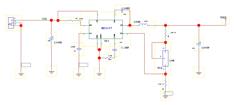
I’ll show you how to make the step-down DCDC converter on the FlowerPad-NoPlated protoboard, and finally power a 5W HB LED.
This converter based on MP2307. This device integrates 100mOHM MOSFETS that provide3Aof continuous load current over a wide operating input voltage of 4.75V to 23V. I used a 12V DC dapter as input in this converter. So the output can be adjusted from 1.2V to 10V by a 10Mohm potentiometer. One voltage meter is fixed for real time voltag display. It is a good tool in electronic DIY. Now, please follow my step to starting your DIY.
Step 1, You will need

TOOLS
- soldering iron
- pliers
- small screwdriver
- tweezer
- solder
- snips
PARTS
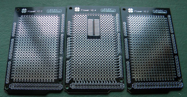
- 1pcs x ElecFreaks non-plated Flower protoboard
- 1pcs x HP LED
- 1pcs x mini voltage meter
- 1pcs x 10Mohm potentiometer
- 1pcs x MP2307
- some capacities and some capacities ( please refer to the schematic for more details)
Schematic
Step 2. Soldering the MP2307
")
The red marking numbers shown connectivity between the SOIC pad and Flower pad. Non-plated pad design make pads on different layer is independent. Please note that the SOIC pad connect with bottom layer flower pad. You need to make via if you want to connect top and bottom layer pad. The method will be mentioned below.
Step 3 Fixed DC connector(J3???/h4>
")
")
The above picture is diagram of the electronic connections. Please fix the J3 connector as shown in the picture. The connector pin is flat, so you need to drill two larger holes as following picture shown.
")
Step 4 Wiring on double side use solder
We recommend the left soldering copper when‘make a bridge between two pads’ use solder.
")
Refer the diagram to wire on double side. Please note that the red line indicatet top layer trace,and blue line indicate bottom layer trace.
As the following picture shown, move the soldering copper in horizont direction to disconnect two pads,and move in vertical to connect. Please measure whether the trace is conduction when you complete it every time. It will increase your success rate.
")
Step 5 Making via on Flower protoboard, connect top and bottom pad.
")
We need make 4 vias on this board. At first, bend a metal wire as picture1 shown. The meatl wire can be LED’s leg or other things your can find easily.Then solder it on top layer.
Step 6 solder it on bottom layer. You must fast enough to solder bottom layer,otherwise you may dissolve top layer solder.
")
Step 7 Making your connector solder more reliable.
Connectors usually need to be able to withstand multiple – plug. It means we need to solder it more reliable. As following picture shown, use a knife to scratch the black solder mask. You can see a square shape pad.
")
It has more solder area than primary Flower pad. Larger soldered dot have more soldering intensity.
")
Step 8 Fixed voltmeter
")
The voltmeter has a wide voltage measurement range from 3.2 to 30V. Two mounting holes make you can fix it onto Flower board easily. The red line connect to output anode, and the black connect to cathode.
")
Step 9 Power and debugging
Double-check the circuit again before power on it. Make sure there is no any short current between IC pins. Check whether connection between components is reliable. Finally???confirm the input and output poles is no short circuit. Power on the converter then rotate the potentiometer,you can adjust the output voltage, and the voltage display on voltmeter. I use this DCDC converter to power a 5W HB LED over 30 hours. As the tested result, it works stable and reliable.
")

Thant’s All. Thanks and Enjoy !!
Thant’s All. Thanks and Enjoy !!