

RPI TFT LCD Adapter User Guide
January 11, 2019
Mathias Wilhelm’s review about Octopus 9DOF module
January 11, 2019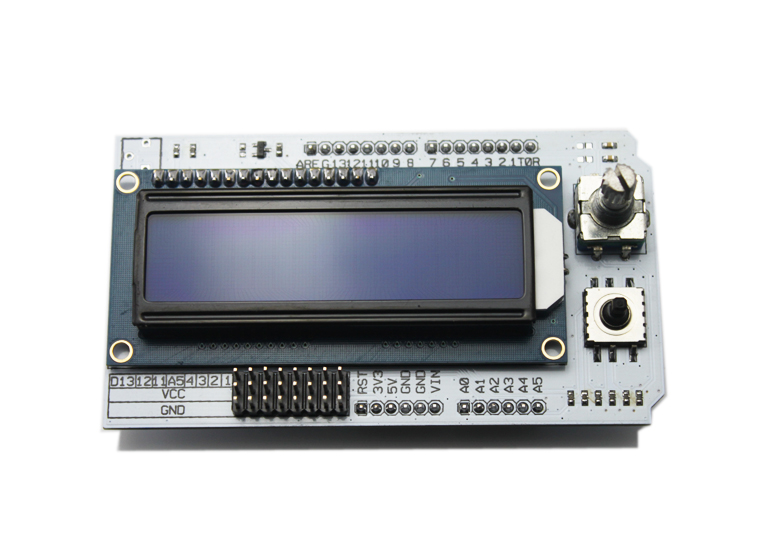
Firstly we want to give a big thank you to Mathias Wilhelm. You are a really remarkable engineer and reviewer, having helped us complete several well-received reviews, including Mathias Wilhelm’s Review About Octopus 9DOF Module , A Review About RGB Matrix Shield , A Review About Freaduino And Redboard From Sparkfun . No words can express our sincere gratitude, and benefiting from the sharing of your effort to the hobbyists in the open hardware community, more electronics enthusiasts are now willing to perform product test for us. As long as you meet our requirements for the reviewer, please feel free to contact us. Now let’s take a squint of today’s sharing, Mathias Wilhelm’s review about LCD shield So a standard 16×2 LCD in blue – so what? Well on a closer look, there are three elements that turn this LCD shield into a remarkable and useful tool:
1.there is a rotary encoder
2.there is a 5-way digital joystick
3.A1-A5 and D11,D12 and D13 are available with GND and V+
Rotary Encoder
The encoder uses pins D2 and D3 and be used like any other rotary encoder. D2 is used a triggering interrupt and the level of D3 determines if you are turning clock- or counterclockwise.
5-way digital joystick
The joystick uses A0 as analog input and gives the joystick value as a voltage between 0 and 5V. It uses a resistor based voltage divider. This is also the very common way to handle such a joystick.
LCD Pins
The pins D4 to D10 are used for managing the LCD. D10 is controlling the brightness of the LCD. As D10 is a PWM output, writing to it with analogWrite will dim the brightness. A Value of 0 turns the backlight off, the value of 255 turns it completely on.
Unused Pins

using the joystick left/righ switches between ADXL, HMC and ITG sensor
using the joystick up/down switches to servo tester and brightness control