

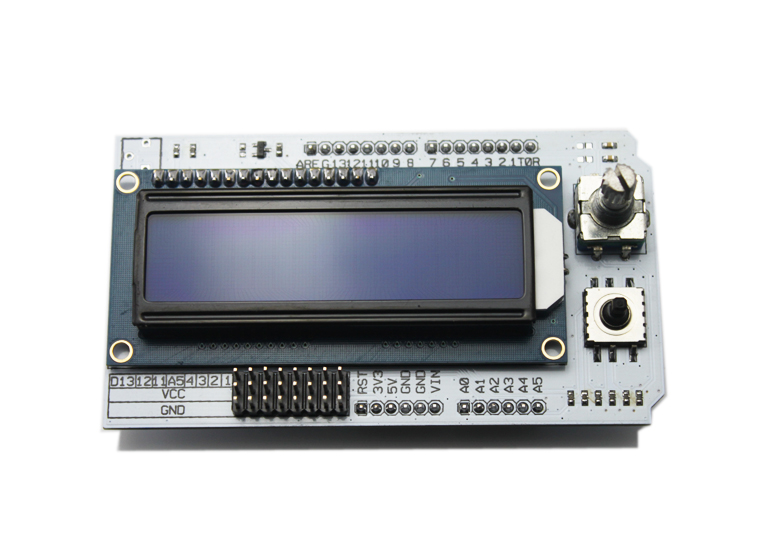
Mathias Wilhelm’s review about LCD shield
January 11, 2019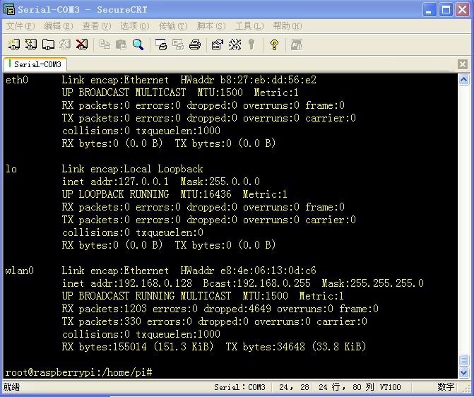
Wireless USB Adapter Configuration User Guide
January 11, 2019
Could you still remember the senior engineer Mathias Wilhelm? Until now, he has written 3 reviews for Elecfreaks customers if counting today’s one. His previous A Review About RGB Matrix Shield , and A Review About Freaduino And Redboard From Sparkfun have been well received and highly praised by the enthusiasts. We are so honored to have such an excellent engineer help us do product test and now we can share his another review about Octopus 9DOF MODULE . We always recruit reviewers, providing free samples to reviewers to perform product test and share their efforts with every member in the open hardware community, aiming to abide by “open” spirit, helping more people in operation. So if you are a review hobbyists, please send an email to us to apply it.
Octopus 9DOF
The octopus 9DOF module is a IMU Module, where IMU stands for “Inertial Measurement Unit”. It comes at a list price of 39$, which is quite cheap compared to other IMU modules I have seen in the market (for Germany, I have to add MWSt (19%) and shipping). The breakout board has three sensor on board that measure the movements of the board:
1.ITG3205: A gyro sensor measuring the rotation of the board
2.HMC5883L: A mgnetig sensor measuing the magnetic field and direction. This gives a nice compass.
3.ADXL345: An accelleration sensor giving the accelleration in three dimensions x,y and z
All three sensors use I2C as communication protocol and the scan of the I2C bus returns three independent devices:
[cce]
I2CScanner ready!
starting scanning of I2C bus from 1 to 127...
... skipped ...
addr:  29 0x1d         addr:  30 0x1e DEV!    addr:  31 0x1f         addr:  32 0x20
... skipped ...
addr:  81 0x51         addr:  82 0x52         addr:  83 0x53 DEV!    addr:  84 0x54
... skipped ...
addr: 101 0x65         addr: 102 0x66         addr: 103 0x67         addr: 104 0x68 DEV!
done
I2C devices found: 3
[/cce]
What I liked with this module is that the three sensors are aligned and labeled nicely and that the orientation is clearly marked and the same for all three sensors. The board is connected to the arduino the way all I2C devices are connected with SCL-A5 and SDA-A4 or the SCL and SDA pins if you use a R3 design /the drawing on the wiki page of elecfreaks is wrong). The device runs on both 3.3V as well as 5V. 
ADXL345
The accelleration sensor shows the normal gravity of my area with its split into the three kartesian axes, so that the total vector length should give the values for g (9.8081 m/s^2 at my location following the Welmec formula). I took some time to find a library that takes care of calibrating the sensor and you can download it in the package including the demo code. I found that for my sensor, the three axis value scale sligtly different so that you may consider compensating that in your code if that kind of precision is needed. The sensor displayed the local gravity within 0.5% accuracy which I consider quite impressive.
HMC5883L
I had tested perviously compass modules and was very disapointed with the outcome. The more I was impressed by this module and its readings. Normal code examples take a shortcut when calculating the heading whilst assuming that the sensor is leveled in x and y. This leads to significant errors as soon as the sensor is tilted. I found a library that does a tilt compensation using the orientation reading of the ADXL345 sensot to determine the tilt of the sensor and to correct accordingly. Due to the alignment fo the sensors, no correction to the axis orientation was neccessary.

ITG3205
Finally the gyro sensor has a neat self-testing feature that allows for a calibration of the device at startup. I also found a library that provides me with the neccessary code. I suggets to keep an eye on the code developed for quadcopters as these use the same sensors for their flight control to profit of the development there.
Demo Code
The demo code provided by Elecfreaks is doing the simple read-out of the sensors so I combined the examples of the three libraries I found into one demo code. The code as well as the libraries can be downloaded here. The output looks like this (the device is pointing North):
[cce]
ITG3205: zeroCalibrating ... done.
ADXL connect data: 229
Connected to HMC5883L, ADXL345 and ITG3205.
ADXL Raw x:    3 y:   18 z:  240 Scaled x:  0.01 G y:  0.07 G z:  0.93 G
HMC5883L Raw:  353.94 (Tilt Compensated):  359.98
ITG3205 Raw x:   14 y:   43 z: -201 Calibrated x:    1.73 y:    1.25 z:  -15.16 T:  25.79 C
ADXL Raw x:   -9 y:   15 z:  246 Scaled x:  0.03 G y:  0.05 G z:  0.95 G
HMC5883L Raw:  355.32 (Tilt Compensated):    0.10
ITG3205 Raw x:  -58 y:  128 z:   -1 Calibrated x:   -3.13 y:    7.37 z:    0.69 T:  26.20 C
[/cce]
Summary
The 9DOF module turns out to be a precise module for a very attractive price. The setup of the device is simple and the code example demonstrates the use. The tilt compensation and the calibration is a bit tricky but that lies in the nature of such a device. I observed an accuracy of less than 0.5% which seems to be quite good for this module.