

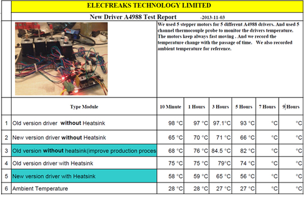
ElecFreaks 3D Printer: A4988 Thermal Design
January 10, 2019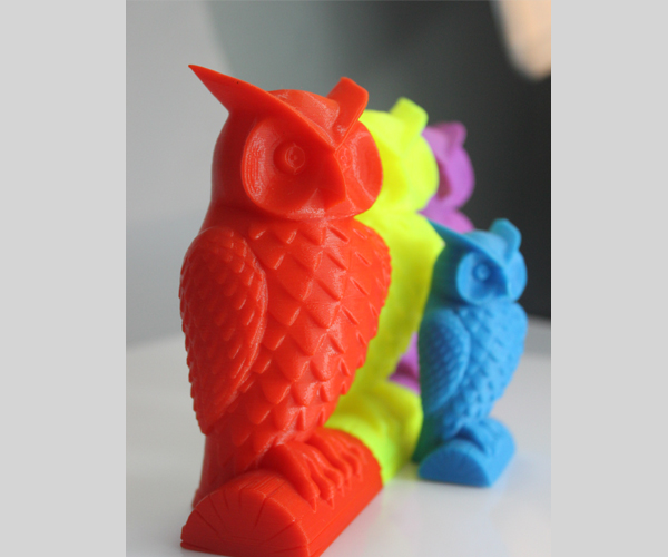
The 3D Printer: Record 1
January 10, 2019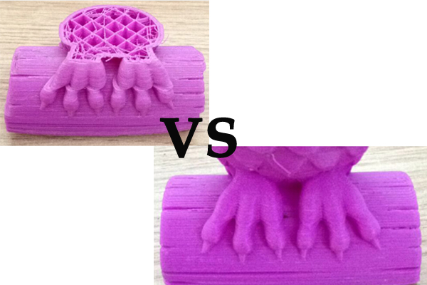
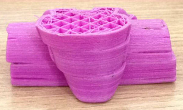
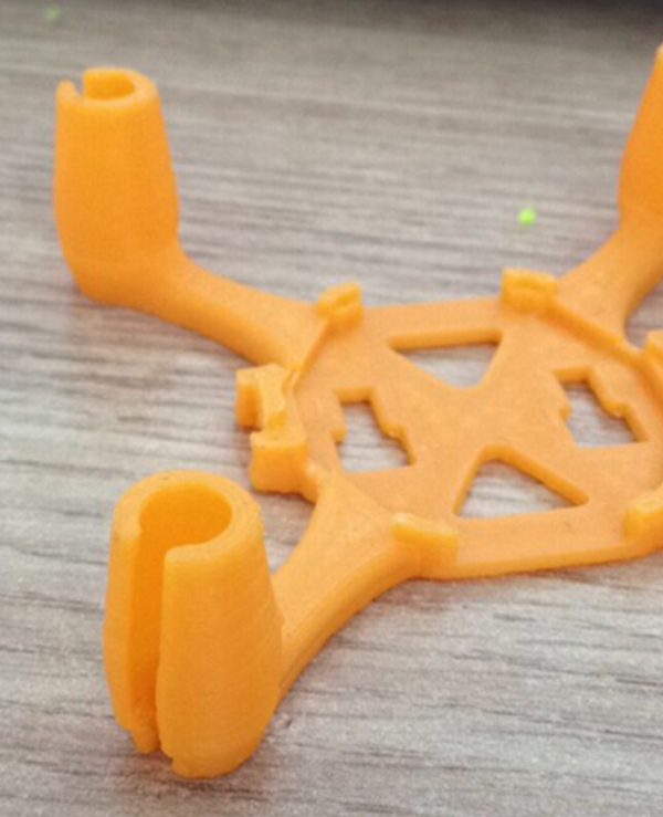
Following the last blog, here we come back with a commonly seen yet critical phenomenon on 3D printer: step losses. In most cases, while printing, they’re reflected in split-level of X and Y directions.
Split-level print
Normal print
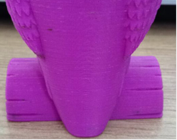
Split-level print
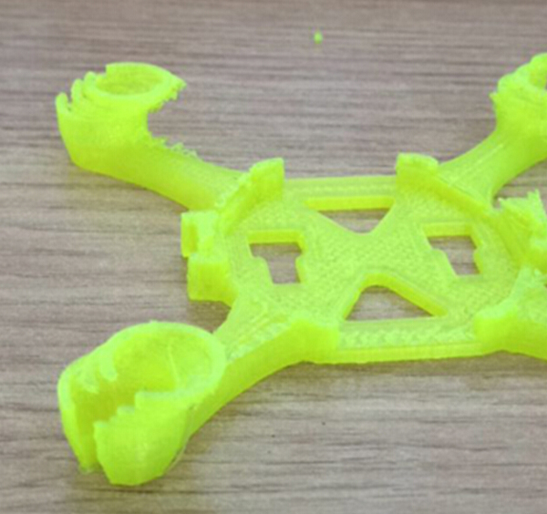
Normal print
Schematic
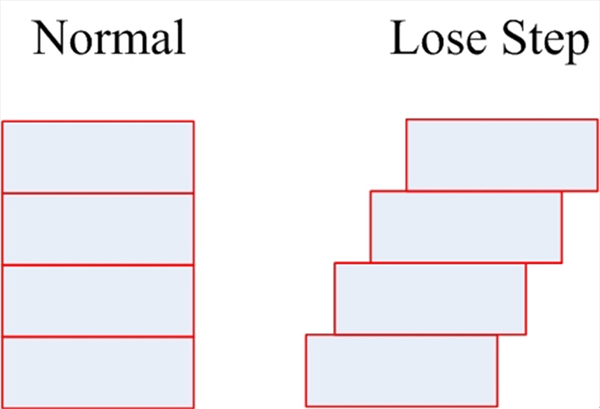
The main reason behind is that after the main control board issues an order, the motor does not arrive at the predetermined position, or it moves too fast to make an accurate stop at the position. The moment when a second order is sent over, which is based on an acquiescence of effective execution of the last order (yet the opposite is true), it leads to an error in base point, thus, split-level happens. The root cause of this problem basically lies in the motor’s false and ineffective following of the main control board’s orders. But what kind of factors exactly will cause the motor’s failure in execution? We analyze from the following aspects:
1. Floppy belt. Too loose a belt could probably contribute to step losses, for instance, if the motor rotates 5 steps but of which, 2 are missing in the belt section, then the actual movement will be 3 instead of the initial 5.
2. Inferior pillow. A poorly-made pillow, rough in surface, could result in great resistance and difficulty in the extrusion head.
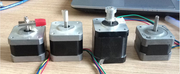
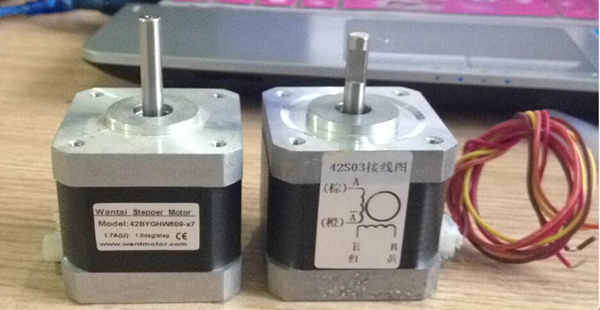
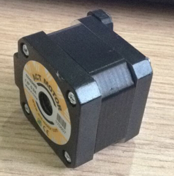
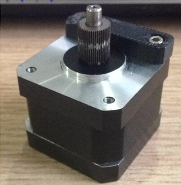
3. Low-quality stepper motor. The output torque may be over small, stepping imprecise.
4. Above all, the leading factor is a lack of motor strength, largely due to the A4988 drive current shortage. With regard to this, another two major factors may take into account when reckoning about split level, one being if the extruder can come up to the predetermined position, the other being if it’s able to stop there. Only the strength of the motor is large enough, can the above mentioned two factors be attained, especially a pinpoint “brake” of the extruder is critically important during high speed printing. To address those concerns, ElecFreaks have worked out some solutions:
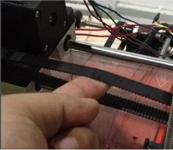
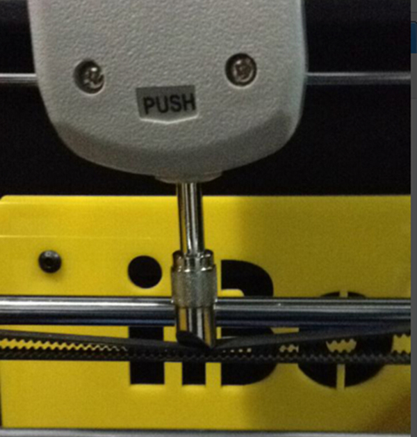
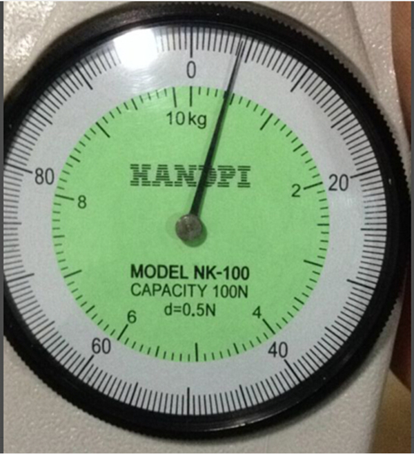
1. To ensure the belt strength on each machine, we use a dynamometer for tension measurement. Take X-axis belt, for example, we use the dynamometer to push vertically from the top down and reads when the upper line hits the lower. From this experiment, we came to a conclusion that 4N is the most appropriate value for it’s just enough to keep off step losses in 150mm per second high-speed sporty mode and over tightness will certainly make the motor overloaded.
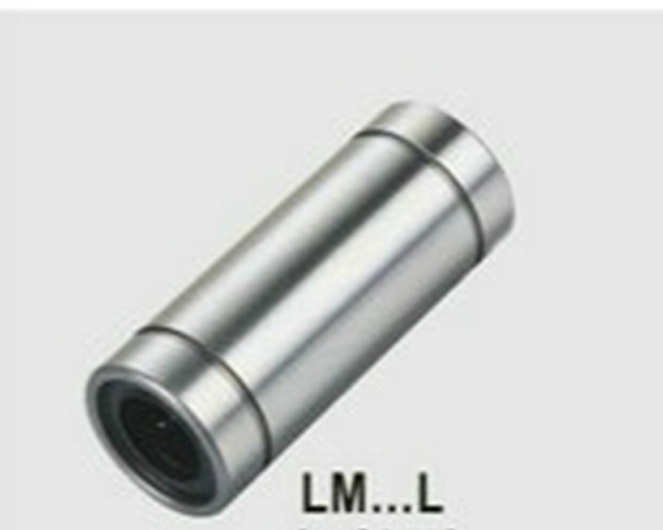
2. We use quality trustworthy pillows. There are hundreds of different types of optical axis on the market, varied in price and quality. To reduce costs, we’ve tried cheap bearings, only to find that some were particularly susceptible to rust, some ended in bearing balls easily falling off, the others performed good at the beginning but badly worn after a while. We chose a desirable pillow from the Taiwan manufacturer among ten or more, after a long-time non-stop printing, it proved to meet our requirements.
3. We adopt durable fine stepper motors. The output torque of motors differs depends on parameters and conversion efficiency even using the same driven current. We finalized an optimized scheme with the minimum driven current yet able to produce the maximum output torque through tests on over five models of stepper motors. The stepper motor, after a period of testing and validation of more than 24 hours, is still able to continue to print stably.
4. We adjust to meet the appropriate A4988 drive current. Different motors have different requirements on current although using parallel torque output. So about exactly how much current is needed all depends. The following content will showcase how to regulate and determine our drive current. We use A4988 as the stepper motor driver. A4988 is a widely acknowledged stepper motor driver chip. You can find it in the famous REPRAP information website: http://reprap.org/wiki/Stepstick. The page demonstrates about how to adjust the drive current in detail and provides a complete PCB schematics and BOM as well. We deploy a current-limiting version 1.5A, BOM follows:
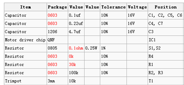
The most important formulas are summarized as follows: For repraps, logic supply voltage (VDD) is 5V. Using the values from the 1.5A table above: VREF max = (TrimpotMaxR/(TrimpotMaXR+R1)) x VDD = (10,000 / (10,000 + 30,000)) * 5 = 1.25V ITripMAX (effectively max motor current) = VREF / ( 8 x Sense_resistor) = 1.25 / ( 8 * 0.1 ) = 1.5625A To calculate amps from measured VREF: A = VREF / 0.8 To calculate VREF required for a target current: VREF = A * 0.8 As can be seen from the above formulas: we only need to adjust the value of the T1 potentiometer to obtain different currents. By slowly increasing the current during long high-speed printing, if the duration can last as long as up to 24 hours without any print problem, we can conclude that the current is large enough. After a week of testing, we finally selected a suitable current (afafmA), which is precisely the value what we’ve been figuring up to support stable print at a speed of 150mm/s. There’s one point to remind you that, calculated by this formula, the value is not very accurate, as it will add some PCB trace resistance, the device errors, etc., so the result is an approximate value. The specific current situation needs instant test.
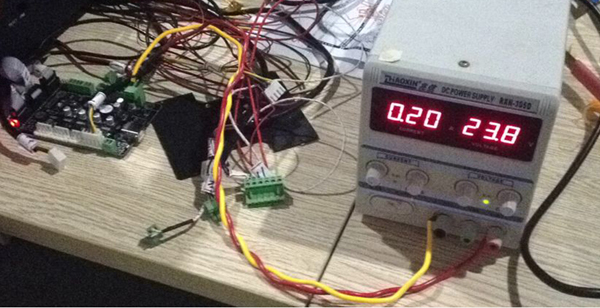
If you intend to improve print speed to a little faster level, you have to further increase the drive current, but as the drive current increases, A4988’s heating also goes up accordingly. Tested in the absence of the cooling fin, when transferring it to 400mA, A4988 gives out tremendous heat, and cannot be functionally used. Question comes again, how do we solve such a problem? We’ve gained much experience to be introduced in our next blog. See you!