Trimpot (or potentiometer) is a kind of common pressure adjustment components. In the following experiment, we are going to read output voltage on trimpot and display it by Micro:bit 5*5 LED screen with bar graph.
1 x Micro:bit Board
1 x Micro-B USB Cable
1 x Microbit Breadboard Adapter
1 x Transparent Breadboard – 83 * 55 mm
1 x 10K Trimpot
1 x Breadborad jumper wire 65pcs pack
If you want to buy all components above, you may need Elecfreaks Micro:bit Starter Kit.
Microsoft Makecode Online Editor
Major Components Introduction
Trimpot is a kind of adjustable electronic components. It consists a resistance and a rotary or sliding system. When add an outer voltage on the two fixed contact spots of resistance, by changing the place of contact spots on resistance with rotary or sliding system, a voltage with certain relationship with the place of movable contact spot is formed between movable contact spot and two fixed contact spots. Most of the time, it works as a voltage divider. 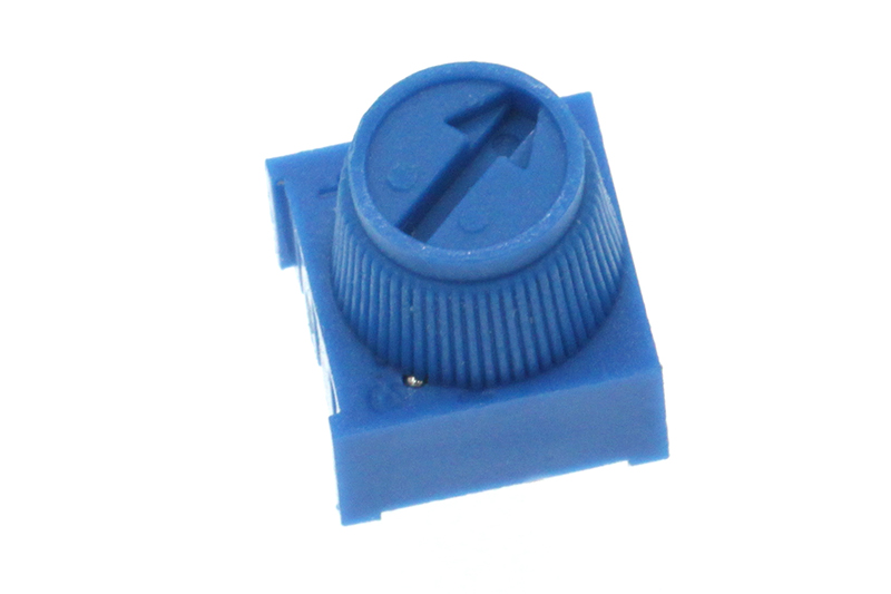
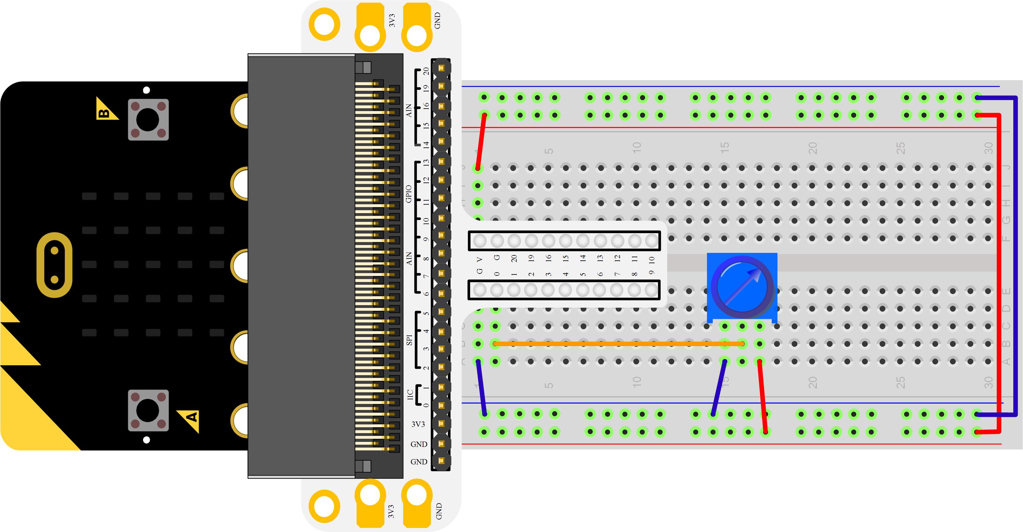
Connect your components according to the picture below: 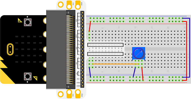 After connection, you will see:
 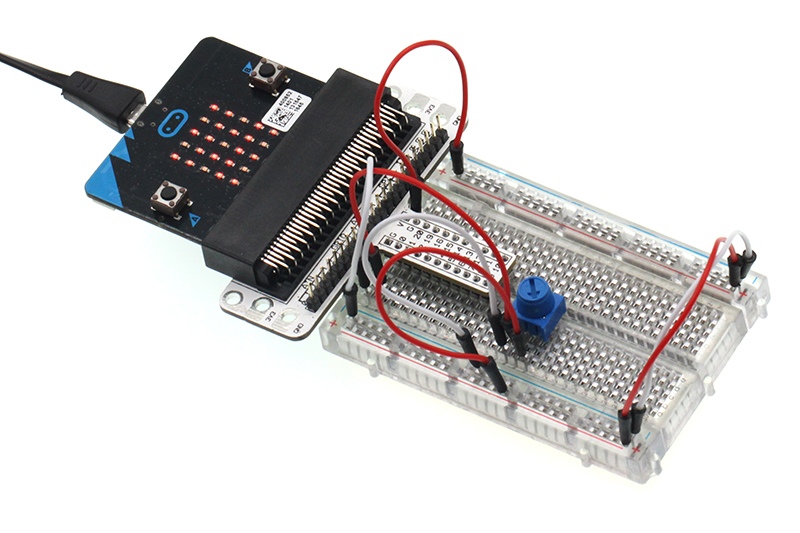 Rotate trimpot button, then output voltage will change from 0V to 3.3V as with the rotation of the button.
Click to openMicrosoft Makecode, write your code in the edit area. We would like to suggest you to write code by yourself first. Of course, you can see the whole program in the link below. Just click the Edit on the right top corner , and then click Download on the right bottom corner to download code into Micro:bit.
plot bar graph Displays a bar graph of the numbers you say. A bar graph is a kind of chart that shows numbers as lines with different lengths. analog read Read an analog signal (0 through 1023) from the pin you say.
Rotate trimpot button, voltage value will be displayed on Micro:bit 5*5 LED screen with bar graph. When voltage read out to be “0”, LED screen display a pixel spot only. While the voltage becomes 3.3V, LED screen will be fully illuminated. 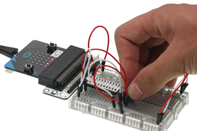
If we want to use trimpot to adjust the brightness of a LED, then how to design circuit and program? Your further discussions or comments are welcomed!
Start Your Micro:bit Programming Trip ELECFREAKS Micro:bit Starter Kit Experiment 01:LED ELECFREAKS Micro:bit Starter Kit Experiment 02:Button ELECFREAKS Micro:bit Starter Kit Experiment 04:Photocell ELECFREAKS Micro:bit Starter Kit Experiment 05:RGB LED ELECFREAKS Micro:bit Starter Kit Experiment 06:Self-lock Switch ELECFREAKS Micro:bit Starter Kit Experiment 07:Temperature Sensor ELECFREAKS Micro:bit Starter Kit Experiment 08:Servo ELECFREAKS Micro:bit Starter Kit Experiment 09:Buzzer ELECFREAKS Micro:bit Starter Kit Experiment 10:Motor ELECFREAKS Micro:bit Starter Kit Experiment 11:Rainbow ELECFREAKS Micro:bit Starter Kit Experiment 12:Accelerometer ELECFREAKS Micro:bit Starter Kit Experiment 13:Compass ELECFREAKS Micro:bit Starter Kit Experiment 14:ambient light