Joystick:bit V1(EF03407)
Contents
13. Joystick:bit V1(EF03407)#
13.1. Introduction#
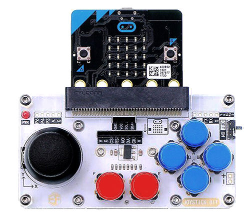
Joystick:bit is a game joystick based on Micro:bit. On the board, it has integrated a joystick and 6 undefined keys. It is very convenient for users to extend different communication modules because it has extended connectors like GVS, IIC, SPI, UART. Besides, it has built-in power switch and outer power connector. It is very good to use.
13.2. Packing List#
1 x Joystick:bit
13.3. Features#
Develop Environment:Javascript / Makecode / Microsoft Touch Develop / Python.
Support UART serial port.
Support GVS-Octopus electric brick.
Integrated a joystick and 6 undefined keys.
Support the extension of IIC module.
Support the extension of SPI module.
Internal Power Input Voltage: DC 3.9V-4.5V
External Power Input Voltage: DC 3.9V-18V
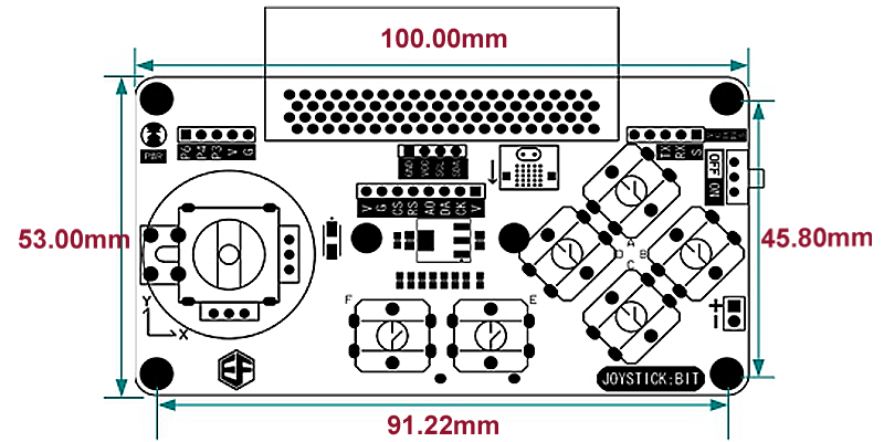
Size: 103.00mm X 64.00mm
Weight: 54 g
13.4. Application#
Support Bluetooth 4.0 device(based on micro:bit)
Support GVS connector, compatible with modules of ElecFreaks Octopus electric brick series.
Remote control smart cars, balance cars.
Users can use it to develop remote control robotics, robotic arms, etc..
13.5. Definition of Pins#
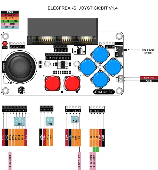
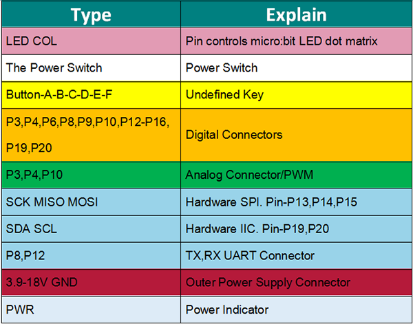
More Details about Some Pin Connectors#
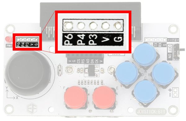
1.G / V(3.3V) / P3 / P4 / P6 are connectors for GVS electric bricks. Among it, P3 / P4 are connectors for analog / PWM / digital connectors, which can help you connect servos and various sensors conveniently.
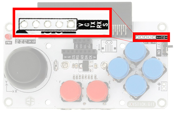
2.UART Connector: V (3.3V) / G / TX / RX / S are serial port connectors. It is compatible with the common wireless communication modules like HC08 / HC11.
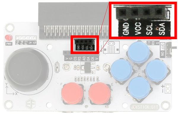
3.I2C Communication Connector: GND / VCC(3.3V) / SCL / SDA are standard I2C connector. It is compatible with 3.3V I2C sensors and devices.
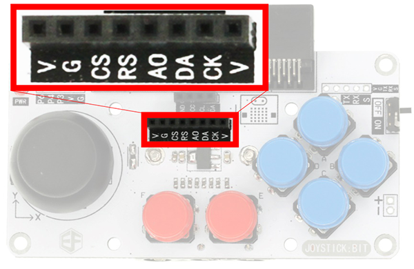
4.SPI Communication Connector:V / G / CS / RS / AO / DA / CK correspond to the connector of TFT 1.8 inch LCD module. It can directly compatible with TFT 1.8 inch LCD module, including SPI communication connector on micro:bit board.
13.6. Dimensions#
13.7. Program#
Code Example:
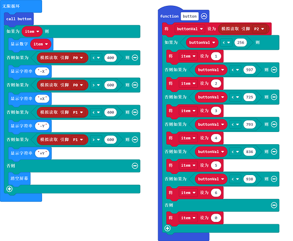
Press button “1”, LED displays “1”.
Press button “2”, LED displays “2”.
Press button “3”, LED displays “3”.
Press button “4”, LED displays “4”.
Press button “5”, LED displays “5”.
Press button “6”, LED displays “6”.
Push joystick upward along “Y” axle, LED displays “+Y”.
Push joystick downward along “Y” axle, LED displays “-Y”.
Push joystick to the left along “X” axle, LED displays “+X”.
Push joystick to the right along “X” axle, LED displays”-X”.
Please refer to the link here: https://makecode.microbit.org/_ibCFsHHWUFKh .
Or, you can download directly from the page below.
13.8. More Information#
For more details, please log on: http://www.elecfreaks.com.