Lesson 02 Button
Contents
5. Lesson 02 Button#

5.1. Introduction:#
In our previous experiment , we have learned how to use Micro:bit to control 2 LEDs and make them twinkle alternatively. This time we are going to use a button to control LED flash. That means when we press down the button,the 2 LEDs flash in turns; when release the button, the LEDs stop flashing.
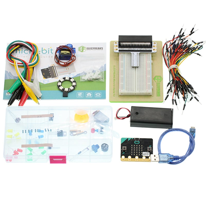
5.2. Components List:#
Hardware:#
1 x Micro:bit Board
1 x Micro-B USB Cable
1 x Microbit Breadboard Adapter
1 x Transparent Breadboard - 83 * 55 mm
2 x LED
2 x 100 Ohm Resistors
1 x Momentary Pushbutton Switch
n x Breadborad jumper wire 65pcs pack
Tips: If you want to buy all components above, you may need Elecfreaks Micro:bit Starter Kit .
5.3. Major Components Introduction#
Momentary Pushbutton Switch#
This is a common component for controlling electronic devices. It is mostly used to connect or cut off the control circuit, it can achieve the control for motors or other electronic equipments.
Momentary Pushbutton Switch usually stays on. When it is pressed down, the circuit is connected; when it is released, it will bounce back to the status of disconnection.
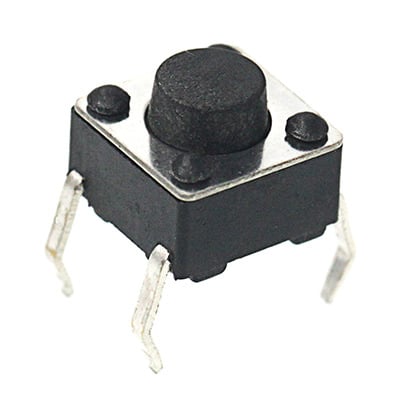
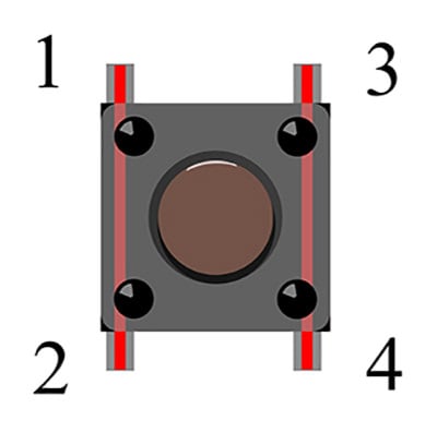
Momentary Pushbutton Switch has 4 pins which can be divided into 2 groups: pin 1 short connects pin 2, pin 3 short connects pin 4.
5.4. Experimental Procedure#
Hardware Connection#
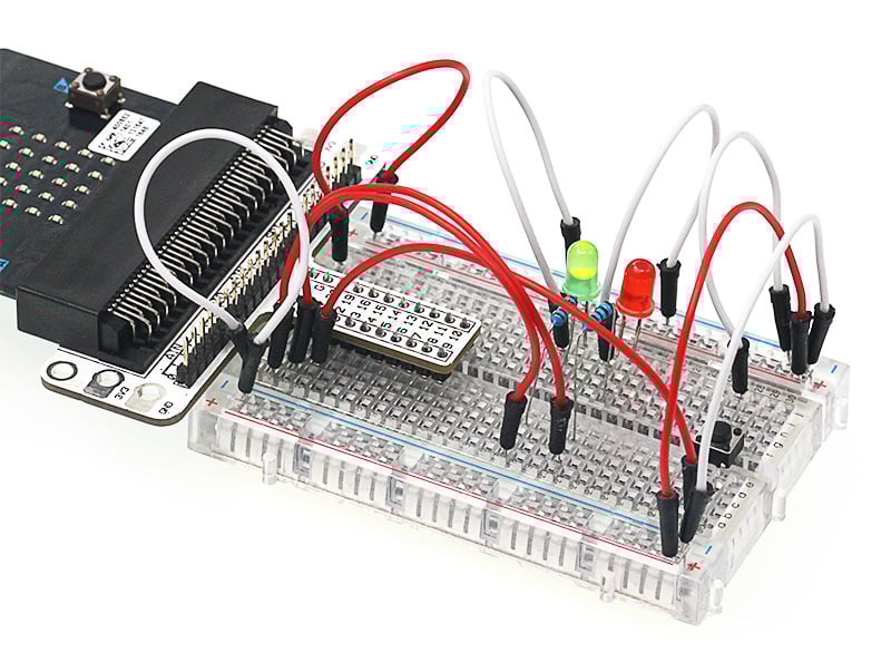
Connect your components according to the picture below:
1.Connect the shorter leg with the GND.
2.Connector the longer leg with the P0 and P1 ports through the Resistor.
3.Connect the Momentary Pushbutton to P2 port.
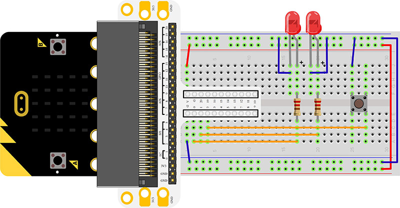
You would see as below after you finish the connection:
Software Programming#
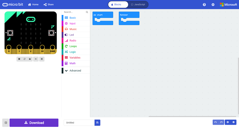
Click to open Microsoft Makecode, write the following code in the editor.
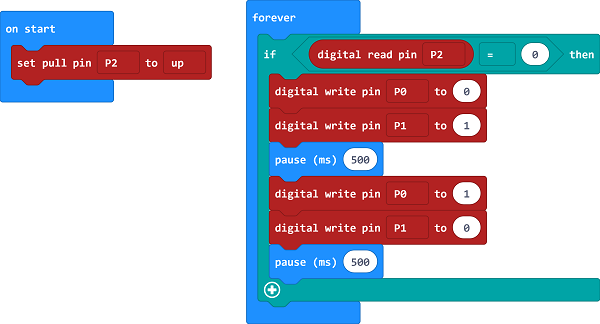
Program as the picture shows:#
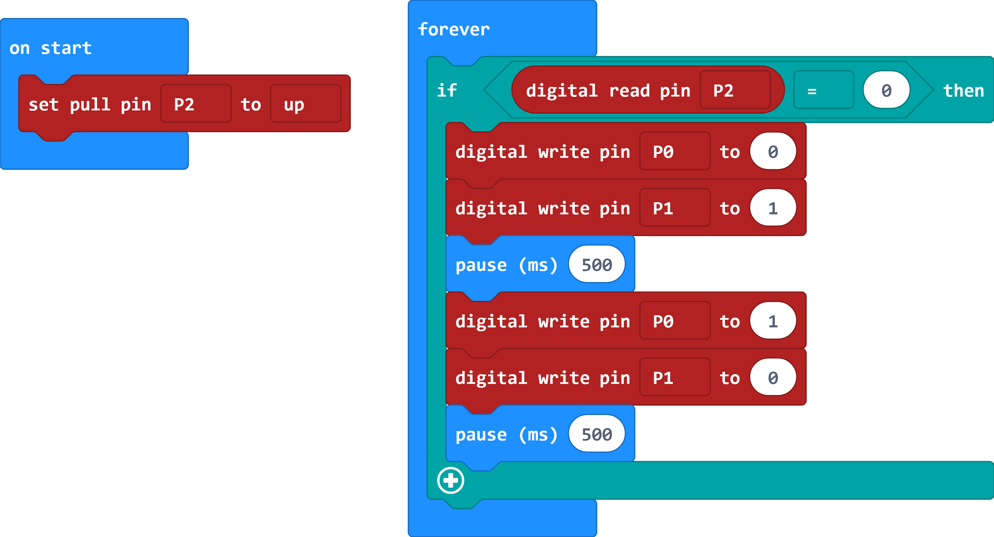
Details for the code:#
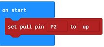
1.Set pin P2 to the high potential in the bricks of “on start”.
2.Read the status from P2 to check if the button is pressed, if yes, digital write signal 0 to P0 port to turn off the LED; digital write signal 1 to P1 port to turn on the LED, then set the pause in 500ms; digital write signal 1 to P0 port to turn on the LED; digital write signal 0 to P1 port to turn off the LED, then set the pause in 500ms.
Reference#
Links: https://makecode.microbit.org/_T585WeYwVWtv
You can also download the links directly:
5.5. Result#
When the button is pressed, you can see the 2 LEDs flashing alternatively; When the button is released, they would stop flashing. If not, you need to go back and check your operations.
5.6. Exploration#
If we want to light on the red LED when press the button and light on the green LED when release the button, how can we program?