case 24 Game bit
Contents
27. case 24 Game bit#
27.1. Put together the Game:bit!#
Let’s figure out where all those screws are supposed to go.
27.2. Products Link#
27.3. Goals#
Assemble the game:bit.
Try not to break it.
Helpful Hint: Toggle through pictures for each step for more photographic detail!
27.4. Materials#
1 x Game:bit kit
1 x Screwdriver
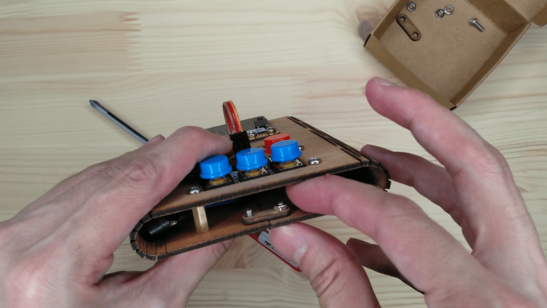
Step 1 – Buttons!#
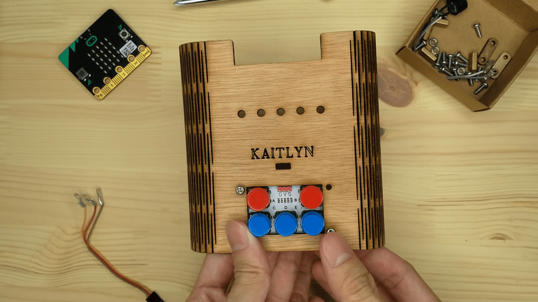
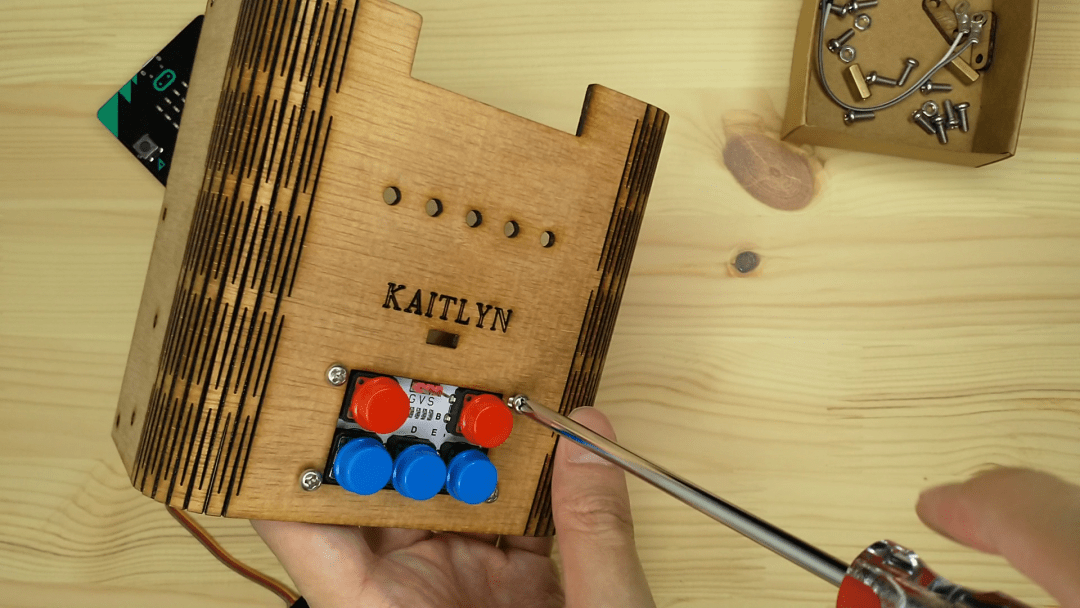
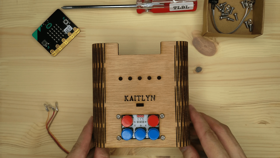
Attach the ADKeypad first with the red buttons on top.
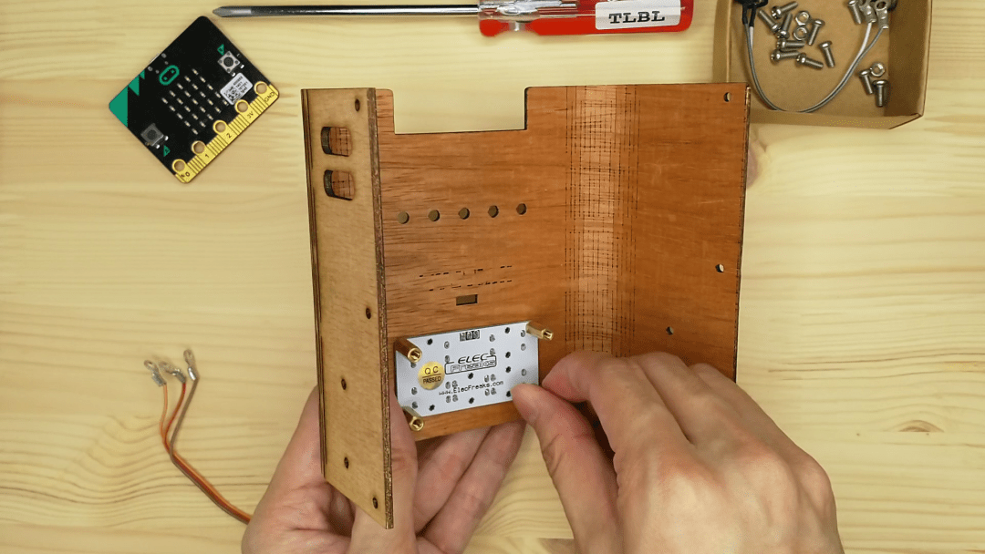
Screw the 4 corners in and secure them at the back with the golden standoffs
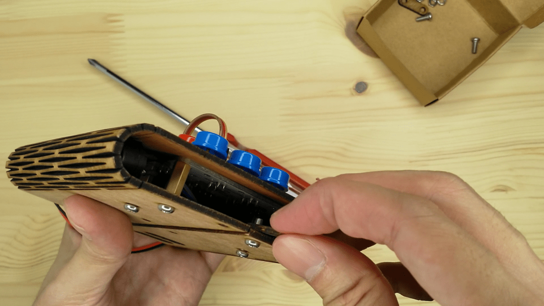
Step 2 – Wire it up!#
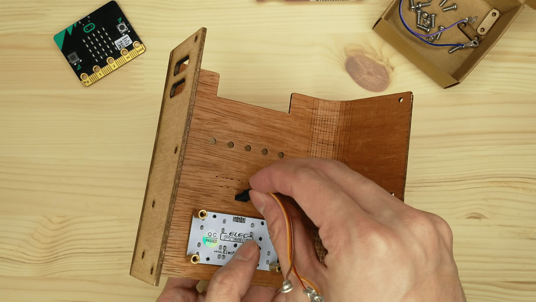
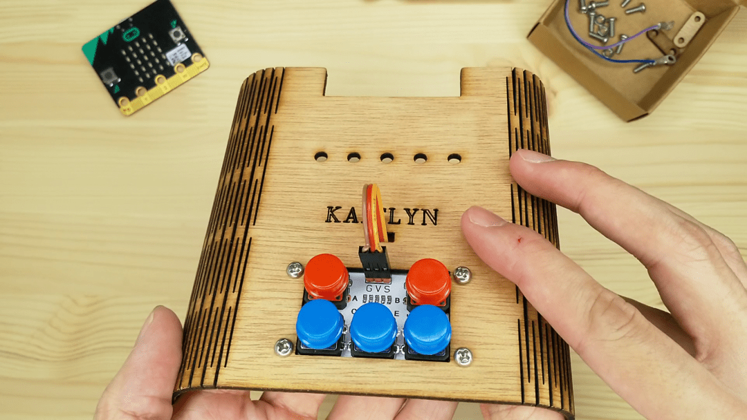
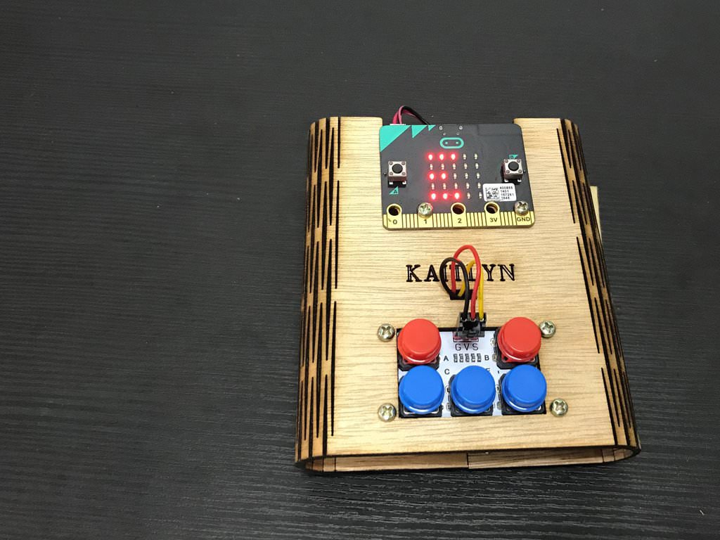
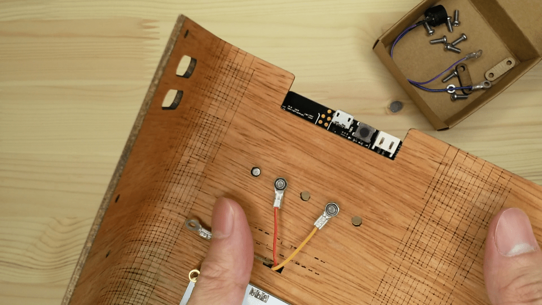
Thread the tri-coloured wire through the hole and attach it to ADKeypad. Brown to G (ground), red to V (voltage) and orange to S (signal).
The colours of the jumper wires don’t actually affect how the electronics work. But it is good practice to follow a colour convention so that you can easily identify where which cables are attached to.
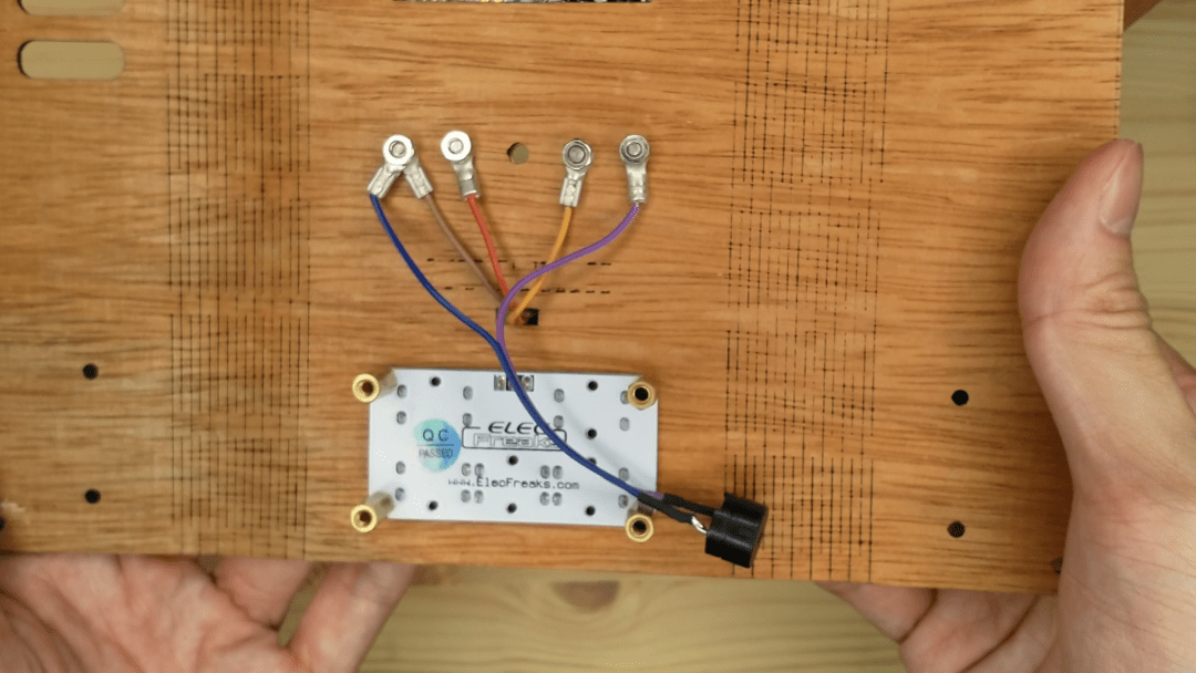
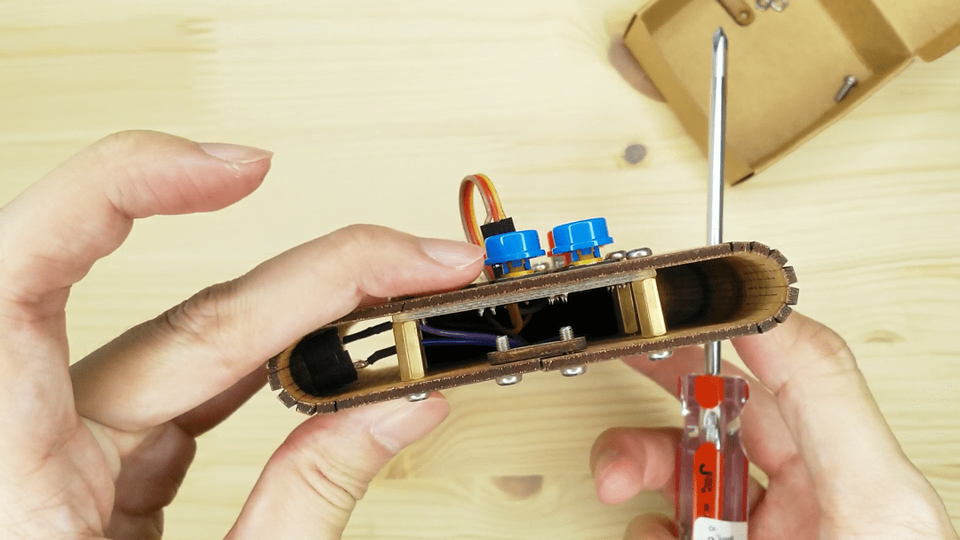
Step 3 – Wiring Firing#
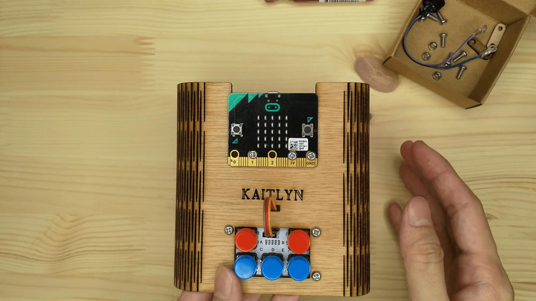
Position your micro:bit at the top and on top of your shell.
Place a screw into the P1, 3V and GND holes of the micro:bit. We’re going to communicate with our ADKeypad through P1 of the micro:bit.
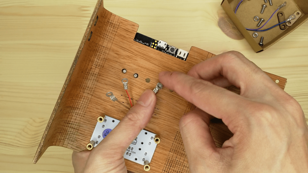
On the back, secure the ring terminal of the orange (S) wire from the ADKeypad to the screw on P1 using a nut. Do the same for the red (V) wire with the screw attached to 3V.
Position the brown (G) wire to the GND screw but don’t attach it yet!
Step 4 – Add a Buzzer#
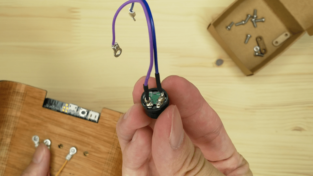
The buzzer has both a positive and negative wire! You can find markings on the green bottom of the buzzer. Take note of which colour is positive (+) and which is negative (-). The power supply capabilities and parameters, which better define how you can use the GND and 3V rings.
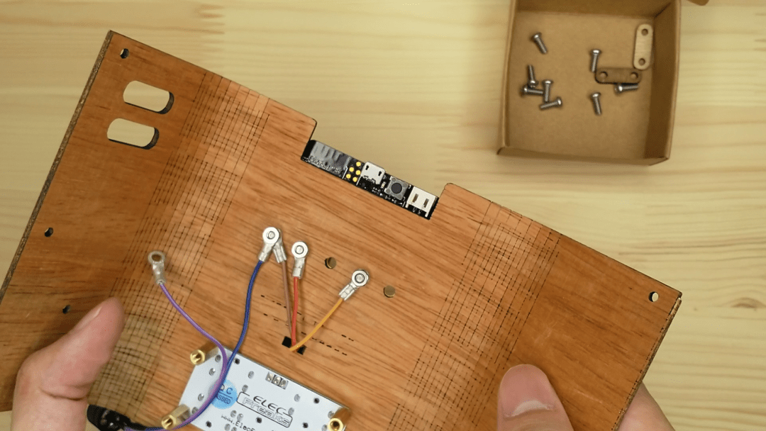
Attach the negative wire to the GND screw above the ring terminal from the ADKeypad. Bolt it in tight!
Attach the positive wire to P0 of the micro:bit using the same screw and nut method.
Take note that the buzzer will only work with the micro:bit when you attach it to P0! You won’t be able to use the makecode Music blocks otherwise.
Step 5 – Battery Powered#
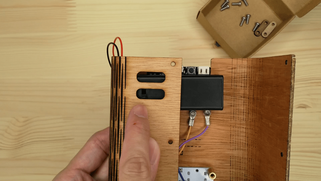
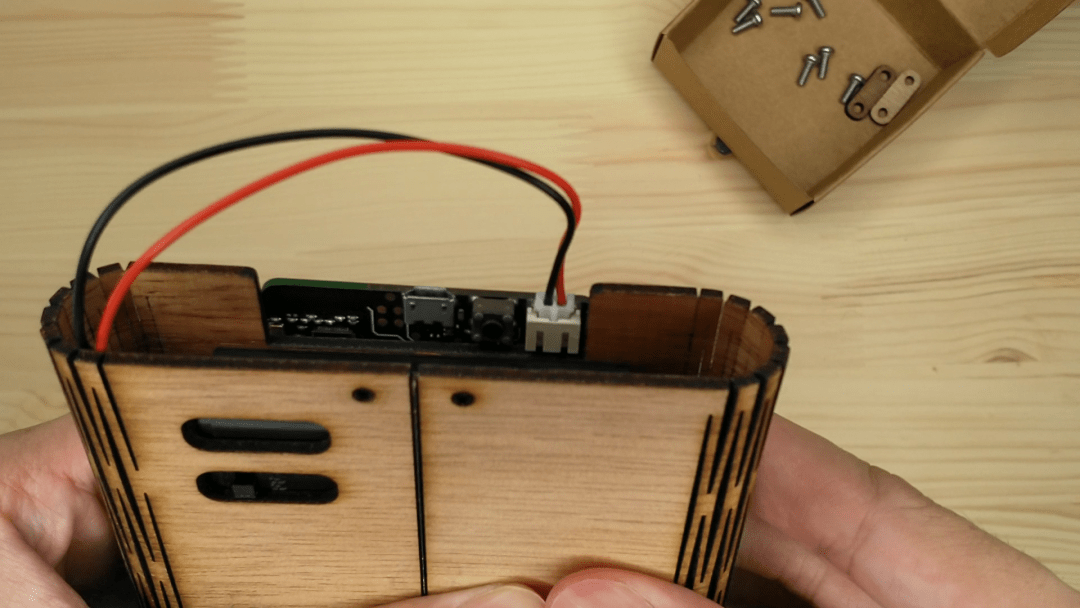
Last thing to go into your game:bit will be your battery pack!
Add two AAA batteries into your battery pack.
Position your battery pack horizontally in the game:bit so that the On-Off switch is accessible from the hole in the back.
Step 6 – Closing Time#
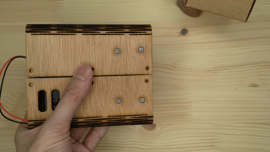
Close up the game:bit and align the 4 holes at the back to the standoffs securing the ADKeypad.
Screw down into the standoffs to secure the back.
Step 7 – Closing Time#
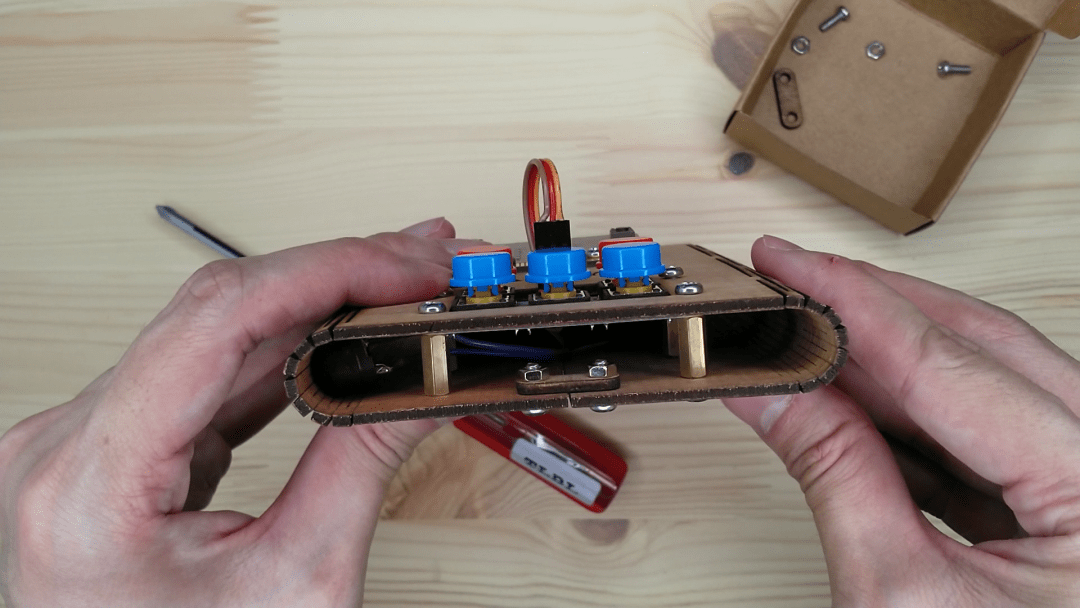
Screw two screws into the two holes at the edge of the shell with the lock holder behind. Secure them with nuts.
Repeat on the other edge of the shell.
The lock holder helps to hold everything together so don’t lose it! (Of course this advice is given right at the end of the instructions)
Cool stuff!#
Now you’ve gotten your game:bit fixed together – get your game on and start coding! Follow along with our tutorials and make cool games like Avoid the Asteroids, Maze Runnerand Flappy Bird.