case 03 RGB led
Contents
6. case 03 RGB led#
6.1. Introduction#
The RGB LED is a kind of LED which creates light of red, green and blue. In this case, we will let RGB LED flash in red, green and blue.
6.2. Products Link#
6.3. Hardware Connect#
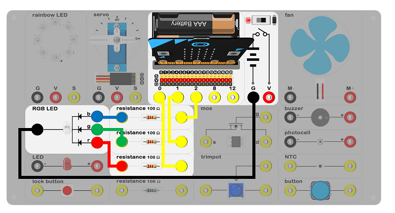
Connect circuit as above picture and put 2 AAA batteries to batteries pack.
6.4. Principles of Circuits#
The GND of slot on micro:bit is into innards of batteries’ GND to generate current loop.
6.5. Introduction of Components#
RGB LED#
The RGB LED is an LED that has 3 integrated LEDs red, green and blue in a single component which is divided into R, G and B channel. It is a wellknown fact that red, green and blue are three primary colors of light. It can mix all color for everything. RGB LED can generate limitless types of color as well. There are 2 types of RGB LEDs, common anode and common cathode. In commoncathode RGB LEDs, the common port connects to GND. While in commonanode RGB LEDs, the common port connects to VCC. Our Experiment Box uses a commoncathode RGB LED.
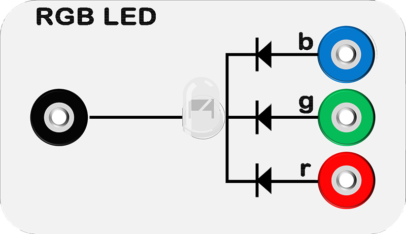
Note: Please note the positive and the negative when you are connecting.
6.6. Software#
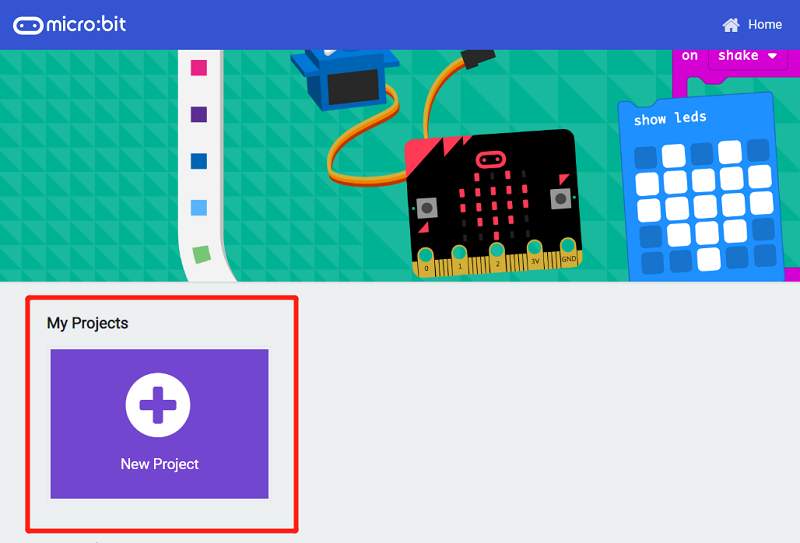
Step 1#
Click makecode https://makecode.microbit.org/#。
Click on “New Project” and set a new Project.
Step 2#
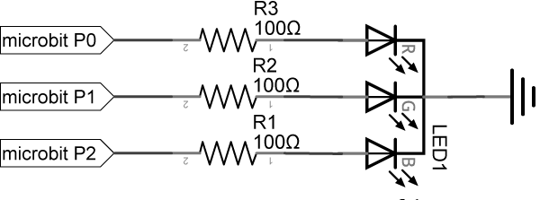
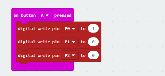
Snap digital write pin into on button A pressed as below picture. Write 1 to the P0 port, 0 to the P1 port and 0 to the P2 port. It means write 1 to R channel of the RGB and write 0 to G & b channel of the RGB. RGB LED is the red light.
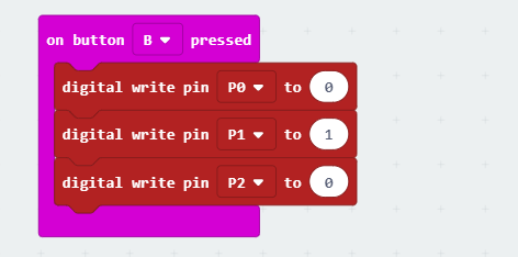
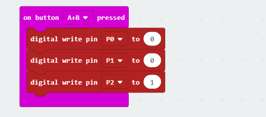
Write code for the green light and the blue light in the same way.
Program#
Program link:https://makecode.microbit.org/_bm1g8RaVuPkb
You also could directly download program by visiting website as below:
6.7. Result#
When the button A be pressed, RGB LED emits red light. When the button B be pressed, RGB LED emits green light. When the button C be pressed, RGB LED emits blue light.
6.8. Think#
What is the color be after mix of red and blue? Show it!