Lesson 12 Accelerometer
Contents
15. Lesson 12 Accelerometer#

15.1. Introduction#
micro:bit has integrated multiple sensors including accelerometer. Today, we are going to use accelerometer to make a level device and display the inclination on RainbowLED ring in bar chart format.
15.2. Component List#
Hardware:#
1 x micro:bit Board
1 x USB Cable
1 x micro:bit Breadboard Adapter
1 x Transparent Breadboard - 83 * 55 mm
1 x 8 RGB RainbowLED Ring
n x Breadborad Jumper Wire 65pcs Pack
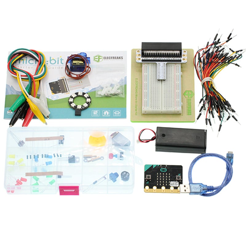
Tips: If you want all components above, you may need Elecfreaks Micro:bit Starter Kit .
15.3. Major Component Introduction#
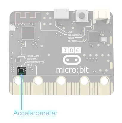
Accelerometer#
There is an accelerometer on your micro:bit which detects the speed change of micro:bit. It converts analog information into digital form that can be used in micro:bit programs. Output is in milli-g. The device will also detect a small number of standard actions, e.g. shake, tilt and free-fall.
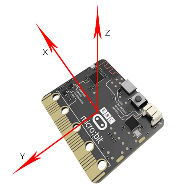
The corresponding X, Y, Z axle direction of accelerometer are showed below:
15.4. Experimental Procedure#
Hardware Connection#
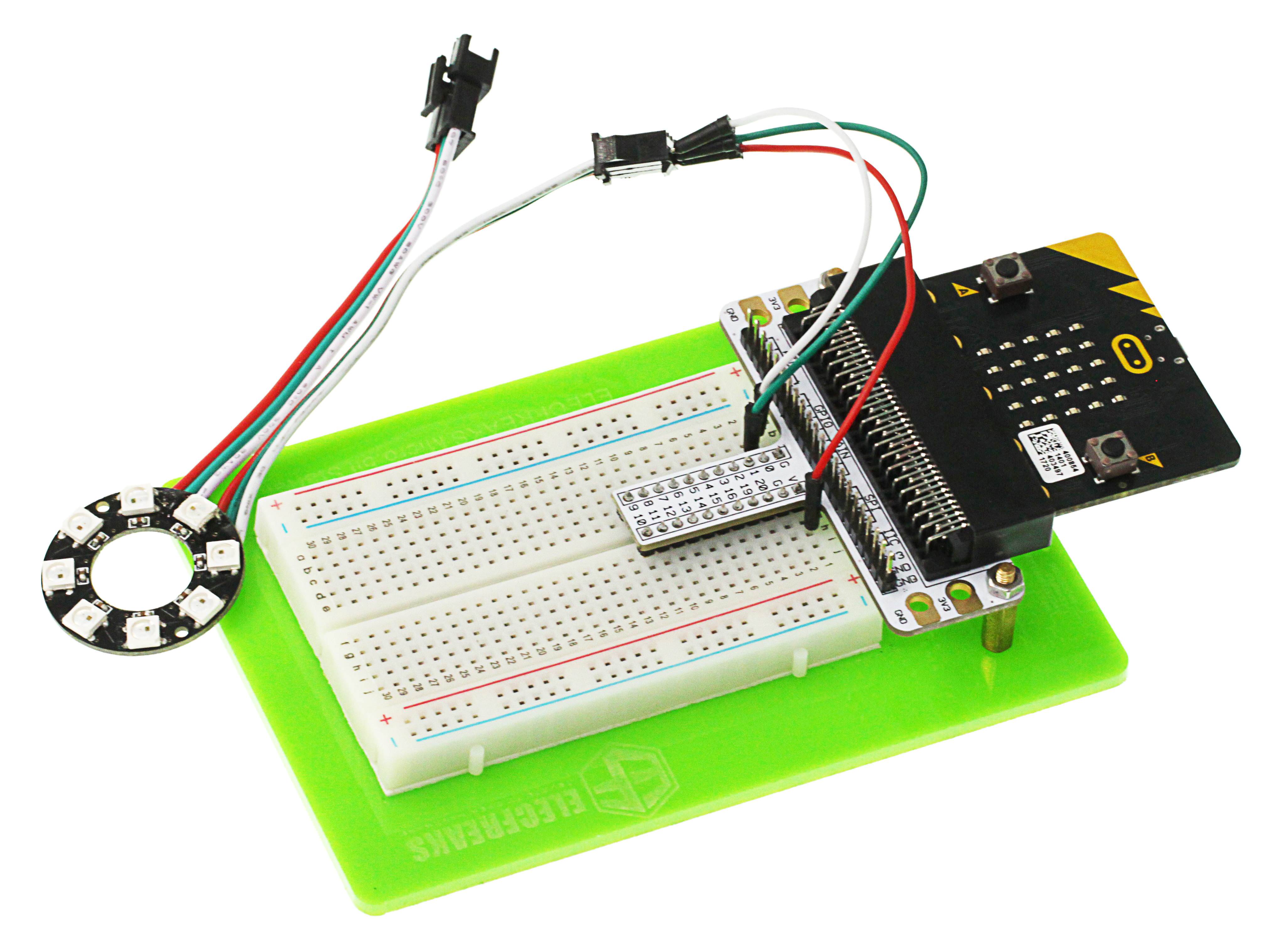
Connect your components according to the picture below:
Connect the signal wire of the LED ring to the P0 port of the breadboard adapter.
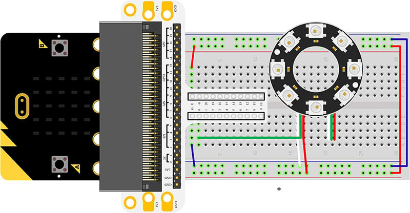
After connection, we can see:
Software Programming#
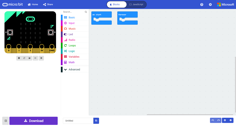
Click to open Microsoft Makecode, write the following code in the editor.(https://makecode.microbit.org/)
Add Package#
Click “Advanced”in the choice of the MakeCode to find more choices.
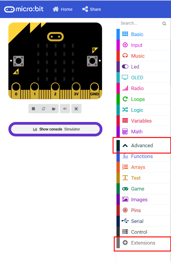
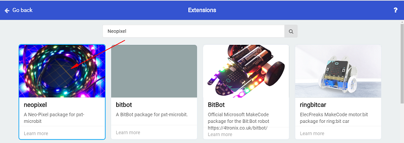
Click “Extensions”, search “neopixel”in the dialog box and then download the “neopixel”.
Program as the picture shows:#
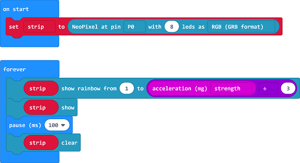
Details for the code:#
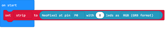
Set P0 port as the pin for LED beads and set it in RGB mode, then light on all the LED.
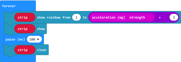
Set the color of the light is changed with the accelerated speed.
Reference#
Links:https://makecode.microbit.org/_0Y07f36Y77sa
You can also download the links directly:
15.5. Result#
The RGB LED ring lights on in different color with the movement of the micro:bit.
15.6. Exploration#
If we want to set 4 of the LEDs to light on in turns, how can we design the circuit and program?