motor:bit Introduction
Contents
2. motor:bit Introduction#
2.1. Introduction#
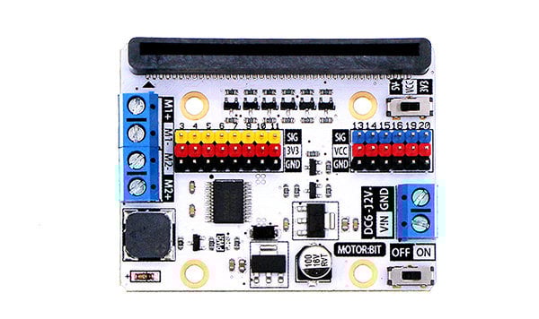
Motor:bit is a motor driving board based on micro:bit. It has integrated a TB6612 motor driving chip, which is used to drive two motors with maximun 1.2A DC single channel current. It has also integrated 12 GVS ports(for connecting OCTOPUS series of electric bricks) and 1 IIC communication port. These ports allow you to extend with various sensors and electric modules. On the board, P3-P7, P9-P10 are IO ports for directly driving 3.3V devices; P13-P16, P19-P20(IIC port) support 3.3V/5V voltage switch. Sliding the voltage switch onboard, it is available to drive 3.3V or 5V devices. Besides, you can play music with the buzzer on motor:bit. Motor:bit is totally designed for DIYers. You can use it to create your own smart car or more funny projects.
2.2. Features#
Support 2 DC motors and the max driving current of each single channel is 1.2A. Extend 14-channel IO ports and lead out it by GVS pins. Among it, 6 ports support 3V/5V voltage switch. With 1 passive buzzer on board.
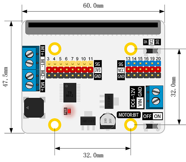
2.3. Parameter#
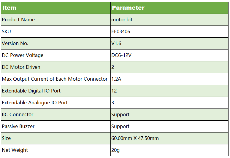
2.4. Dimension#
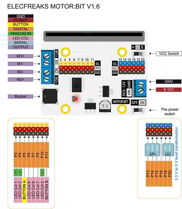
2.5. Definition of Pins#
2.6. Introduction of Major Components#
M1-M2 Motor Connector#
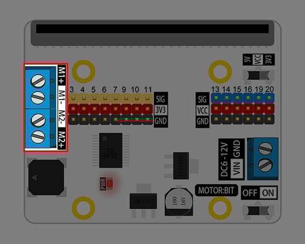
M1 and M2 can separately connect a DC motor with max current of 1.2A.
Passive Buzzer#
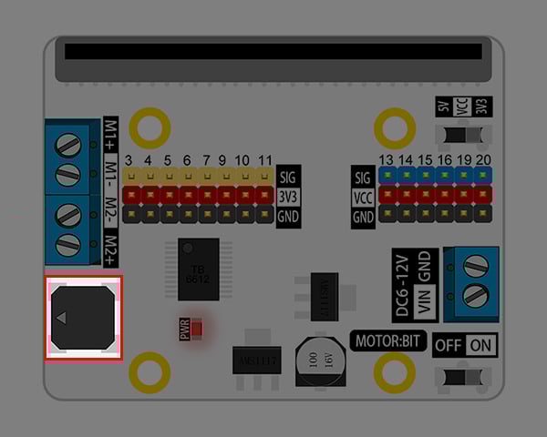
Once a passive buzzer is connected to the P0 port on micro:bit, it can play music.
Power Switch#

Slide the switch to ON, power is connected; slide the switch to OFF, power is disconnected.
Power Connector#
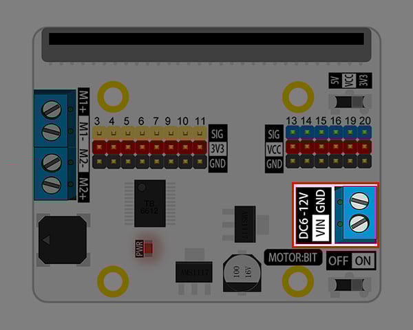
Power connector is available to connect with 6-12V DC power.
VCC Voltage Switch#
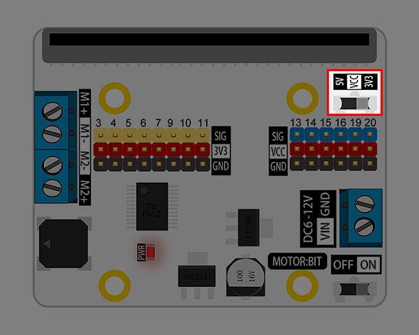
Slide the switch to 5V, then VCC supply 5V power; slide the switch to 3.3V, then it provide 3.3V power. This switch is valid to 6 IO ports only: P13, P14, P15, P16, P19, P20.
G-VCC-S Standard GVS Port#
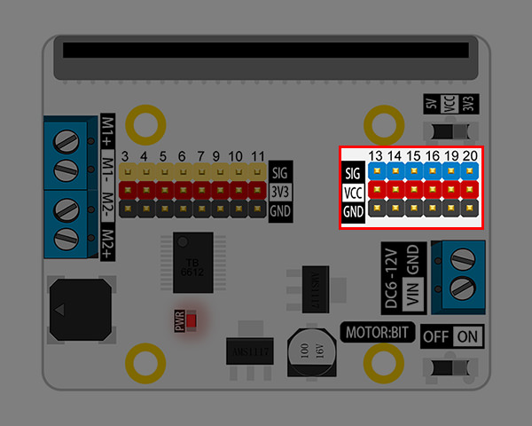
It contains 4 (P13-P16) GPIO ports and 1 IIC communication connector (P19-P20). You can connect 3.3V/5V devices to it according to the voltage change of VCC.
G-3V3-S Standard GVS Port#
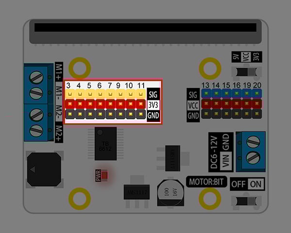
You can connect 8 devices working under 3.3V power supply. Among it, P3, P4, P10 can be used as analogue signal input connectors.
micro:bit Golden Finger Socket#
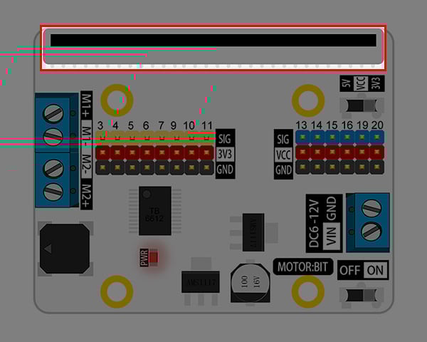
You can plug your micro:bit into this socket.
2.7. Quick Start#
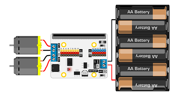
Hardware Assembly#
Connect two TT motors to micro:bit as the picture showed below.
Programming#
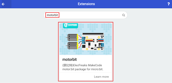
Click Add Package in the code drawer of makecode, then search for the key word motorbit in the dialogue box and click on the searching result to download this package.
Write your code to make two TT motors rotate in turns.
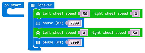
Click the link here to see the whole program: https://makecode.microbit.org/_LsPT31WPH1JD
You can also download it from the page below: